background image

US

GB

GB

GB

GB

GB

GB

GB

GB

GB

GB

GB

GB

GB

GB

GB

When warranty repair is needed, the engine must be brought to an
authorized service dealer or warranty station’s place of business during
normal business hours. In all cases, a reasonable time, not to exceed
30 days, must be allowed for the warranty repair to be completed after
the engine is received by the authorized service dealer or warranty station.

G. MAINTENANCE, REPLACEMENT AND 

REPAIR OF EMISSION-RELATED PARTS

Only warranted engine replacement parts approved by FUJI should
be used in the performance of any warranty maintenance or repairs
on emission-related parts. If other than authorized parts are used for
maintenance, replacement or repair of components affecting emission
control, you should assure yourself that such parts are warranted by
their manufacturer to be equivalent to authorized parts in performance
and durability. FUJI ,however, assumes no liability under this warranty
with respect to parts other than authorized parts. The use of non-
authorized replacement parts does not invalidate the warranty on
other components unless the non-authorized parts cause damage to
warranted parts.

H. PARTS COVERED UNDER THE CALIFORNIA EMISSIONS

WARRANTY

(1) Fuel Metering System 

(i) Carburetor and internal parts (and/or pressure regulator or

fuel injection system).

(ii) Air/fuel ratio feedback and control system, if applicable.
(iii) Cold start enrichment system, if applicable.
(iv) Regulator assy (gaseous fuel, if applicable)  

(2) Air Induction System

(i) Intake manifold, if applicable
(ii) Air filter.

(3) Ignition System

(i) Spark plugs. 
(ii) Magneto or electronic ignition system. 
(iii) Spark advance/retard system, if applicable.

(4) Exhaust manifold, if applicable
(5) Miscellaneous Items Used in Above Systems

(i) Electronic controls, if applicable
(ii) Hoses, belts, connectors, and assemblies.
(iii) Filter lock assy (gaseous fuel, if applicable)

I. MAINTENANCE STATEMENTS

It is your responsibility to have all scheduled inspection and maintenance services performed at the times recommended in the 2005 and later
Owner's Manual and to retain proof that inspection and maintenance services are performed at the times when recommended. FUJI will not
deny a warranty claim solely because you have no record of maintenance; however, FUJI may deny a warranty claim if your failure to perform
required maintenance resulted in the failure of warranted part. The proof which you maintain should be given to each subsequent owner of the
engine. You are responsible for performing the scheduled maintenance described below based on the procedures specified in the 2005 and
later Owner's Manual. The scheduled maintenance below is based on a normal engine operating schedule.

PROCEDURE

INTERVAL

1)  Change engine oil

: Initial 20 hours and every 100 hours afterward

2)  Clean air cleaner (element)

: Every 50 hours

3)  Replace air cleaner element

: Every 200 hours

4)  Clean and adjust spark plug and electrodes

: Every 200 hours

Note: More frequent maintenance may be necessary under dusty, dirty or severe conditions.

RG2800iS(US)̲GU2010  05.4.4  1:35 PM  ページ04

Summary of Contents for RG2800is

Page 1: ...3ZZ9990154 MODEL ...

Page 2: ...3 4 5 6 2 3 4 5 6 1 3 5 4 1 7 2 3 1 2 2 1 1 1 2 2 3 4 1 2 1 3 6 2 2 3 1 1 1 2 8 16 15 13 14 11 12 10 9 1 2 3 4 6 1 1 1 2 5 1 7 1 2 STOP RUN CHOKE 1 2 STOP RUN CHOKE 1 2 STOP RUN CHOKE 1 2 4 3 ...

Page 3: ...durability period Depending on the size of the engine a selection of time periods can be used to measure the Air Index level see below Descriptive Term Applicable to Emissions Durability Period Moderate 50 hours engine from 0 to 80 cc 125 hours engine greater than 80 cc Intermediate 125 hours engine from 0 to 80 cc 250 hours engine greater than 80 cc Extended 300 hours engine from 0 to 80 cc 500 h...

Page 4: ...Consequential damages such as loss of time inconvenience loss of use of the engine or equipment etc Diagnosis and inspection charges that do not result in warranty eligible service being performed Any non authorized replacement part or malfunction of authorized parts due to use of non authorized parts OWNER S WARRANTY RESPONSIBILITIES As the engine owner you are responsible for the performance of ...

Page 5: ...lated part for a period of two 2 years after the date of delivery to the first retail purchaser C WHAT IS COVERED 1 REPAIR OR REPLACEMENT PARTS Repairs and replacement of any warranted part will be performed at no charge to you by an authorized service dealer or a warranty station You may contact the Robin America Inc Customer Service Department at 1 630 350 8200 to obtain the name of the nearest ...

Page 6: ...able iv Regulator assy gaseous fuel if applicable 2 Air Induction System i Intake manifold if applicable ii Air filter 3 Ignition System i Spark plugs ii Magneto or electronic ignition system iii Spark advance retard system if applicable 4 Exhaust manifold if applicable 5 Miscellaneous Items Used in Above Systems i Electronic controls if applicable ii Hoses belts connectors and assemblies iii Filt...

Page 7: ...n ordering spare parts always give us the MODEL PRODUCTION NUMBER PROD No and SERIAL NUMBER SER No of your Product Please fill in the following blanks after checking the production number on your product Location of label is different depending on the product model CONTENTS 1 SAFETY PRECAUTIONS 2 2 COMPONENTS 5 3 PRE OPERATION CHECKS 5 4 OPERATING PROCEDURES 6 5 WATTAGE INFORMATION 9 6 SPARK ARRES...

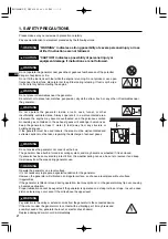
Page 8: ...case piston seizure may occur even if the oil is above the upper level WARNING Pay attention to the wiring or extension cords from the generator to the connected device If the wire is under the generator or in contact with a vibrating part it may break and possibly cause a fire generator burnout or electric shock hazard Replace damaged or worn cords immediately WARNING Do not operate the generator...

Page 9: ...ll bystanders at a safe distance from work areas WARNING If wet wipe and dry it well before starting Do not pour water directly over the generator nor wash it with water WARNING Be extremely careful that all necessary electrical grounding procedures are followed during each and every use Failure to do so can be fatal WARNING It is absolutely essential that you know the safe and proper use of the p...

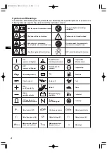
Page 10: ... area Do not connect the generator to the commercial power lines Engine oil ON power and Engine Add oil Battery charging condition OFF power and Engine Alternating current Direct current Plus positive polarity Minus negative polarity OUT position of a bistable push control IN position of a bistable push control Protective earth ground Fuse Choke cold starting aid Engine start Electric start Engine...

Page 11: ...level is low refill with unleaded automotive gasoline Be sure to use the fuel filter screen on the fuel filter neck See Fig 2 e q FUEL FILTER SCREEN w TANK CAP Fuel tank capacity RG2800iS 10 8 liters RG3200iS 10 8 liters RG4300iS 12 8 liters Recommended engine oil Use 4 stroke automotive detergent oil of API service class SE or higher grade SG SH or SJ is recommended SAE 10W 30 or 10W 40 is recomm...

Page 12: ...ontinuously If the engine fails to start return the key to the ON position and wait about 10 seconds then start again Do not turn the key switch to START position when the engine is running to prevent damage of starting motor When starting the engine by recoil starter set the key switch at the ON position and pull the starter handle CAUTION a Make sure the appliance is disconnected b Turn engine s...

Page 13: ... and check the appliance and or generator for overloading After the check and remedy restarting the engine will resume displaying in the normal manner w w Operation hour lamp Lamp red is turned on when changing over into operation hour indication in the LE display e e Voltage lamp Lamp red is turned on when changing over into voltage indication in the LE display r r Frequency lamp Lamp red is turn...

Page 14: ...PPLICATION See Fig 4 4 q q w w a Make sure the voltage indicated in the LE display is the normal level approx 120V This generator is thoroughly tested and adjusted in the factory If the generator does not produce the specified voltage consult your nearest Robin dealer or service shop b Turn off the switch es of the electrical appliance s before connecting to the generator c Insert the plug s of th...

Page 15: ...nd restart the engine c If the engine does not start by usual starting procedures check the oil level Do not remove OIL SENSOR PROBE when refilling with oil Remove oil filler cap on the opposite side of carburetor CAUTION Some appliances need a surge of energy when starting This means that the amount of electrical power needed to start the appliance may exceed the amount needed to maintain its use...

Page 16: ...pressor approx 500 approx 600 Nominal cross section A W G Allowable current No of strands strands dia Resistance Current Amp No mm Ω 100m mm2 No A 1A 3A 5A 8A 10A 12A 15A 0 75 18 7 30 0 18 2 477 2 5V 8V 12 5V Voltage drop 1 27 16 12 50 0 16 1 486 1 5V 5V 7 5V 12V 15V 18V 2 0 14 17 37 0 26 0 952 1V 3V 5V 8V 10V 12V 15V 3 5 12 to 10 23 45 0 32 0 517 1 5V 2 5V 4V 5V 6 5V 7 5V 5 5 10 to 8 35 70 0 32 0...

Page 17: ...ry hot Allow the muffler to cool before cleaning the spark arrester How to remove the spark arrester 1 Remove the flange bolts from the muffler cover and remove the muffler cover 2 Remove the special screw from the spark arrester and remove the spark arrester from the muffler SPARK ARRESTER SCREEN MUFFLER TAIL SCREEN TAIL SCREEN COVER SCREW NUT Clean the spark arrester screen Use a brush to remove...

Page 18: ...SARY FOR THE USER OF THIS GENERATOR TO CONDUCT THE MAINTENANCE AND ADJUSTMENTS ON THE EMISSION RELATED PARTS LISTED BELOW TO KEEP THE EMISSION CONTROL SYSTEM EFFECTIVE The emission control system consists of the following parts The maintenance schedule indicated in the table is based on the normal generator operation Should the generator be operated in extremely dusty condition or in heavier loadi...

Page 19: ...ECTRODES REPLACE SPARK PLUG Note 1 Initial oil change should be performed after first twenty 20 hours of operation Thereafter change oil every hundred 100 hours Before changing oil check for a suitable way to dispose of old oil Do not pour it down into sewage drains onto garden soil or into open streams Your local zoning or environmental regulations will give you more detailed instructions on prop...

Page 20: ...5 2 ENGINE OIL CHANGE See Fig 5 5 w w 1 SIDE PANEL L L R R See Fig 5 5 q q Change engine oil every 50 hours For new engine change oil after 20 hours a Drain oil by removing the drain plug and the oil filler cap while the engine is warm q OIL DRAIN PLUG b Reinstall the drain plug and fill the engine with oil until it reaches the upper level on the oil filler cap Use fresh and high quality lubricati...

Page 21: ... negative terminal Red cable to the terminal Black cable to the terminal Should the connection be made in incorrect manner the engine will be broken CAUTION RED CABEL RED CABEL 5 LESS THAN 131 mm 5 2 in RG2800iS 3200iS 162 mm 6 4 in RG4300iS LESS THAN 114 mm 4 5 in RG2800iS 3200iS 136 mm 5 4 in RG4300iS LESS THAN 71 mm 2 8 in RG2800iS 3200iS 82 mm 3 2 in RG4300iS 1 2 3 4 5 1 6 2 3 4 Battery Base F...

Page 22: ...n Engine Fails to Start Check if engine switch is in its proper position Check fuel level Check to make sure generator is not connected to an appliance Check spark plug for contamination Check engine oil level Check spark plug for loose spark plug cap Turn engine switch to CHOKE position If empty refill fuel tank making sure not to overfill If connected turn off the power switch on the connected a...

Page 23: ... Gasoline Fuel tank capacity L U S gal 10 8 2 9 Rated continuous operation Approx hours Starting system Recoil Dimension Length mm in 537 21 1 Width mm in 482 19 0 High mm in 583 23 0 Dry weight kg lb 54 119 1 EX27 EX21 74 163 1 59 130 1 RG4300iS RG3200iS Electronic Breaker 4 3 3 8 3 2 2 8 265 211 580 22 8 527 20 8 618 24 3 Valve Clearance Intake Exhaust mm in 0 1 0 03 0 0039 0 0012 Note Adjust th...

Page 24: ...ctifier Stepping motor MONITOR C U CONTROL PANEL GENERATOR ENGINE Blk Black Blk Main coil Coil 3 Coil 2 Coil 1 Wiring color cord Blk W Black White Blu Blue Ignition coil Oil level sensor Blu Blu LBlu Light blue Brn Brown Brn W Brown White Grn Green Grn Grn W Green White Org Orange Org DC circuit breaker DC output terminal Gry Gray R Red W White Gry Y Yellow Grn Y Green Yellow W Blk White Black Pur...

Page 25: ...attery Starting motor Diode rectifier Diode rectifier Stepping motor MONITOR C U CONTROL PANEL GENERATOR ENGINE Main coil Coil 3 Coil 2 Coil 1 Oil level sensor DC output terminal Brn Grn Grn Gry Gry Pur Blk Black Wiring color cord Blk W Black White Blu Blue LBlu Light blue Brn Brown Brn W Brown White Grn Green Grn W Green White Org Orange Gry Gray R Red W White Y Yellow Grn Y Green Yellow W Blk Wh...

Page 26: ...ISSUE EMD GU2010 PRINTED IN JAPAN October 2004 CE SK 000 ...

Reviews: