R e c o m m e n d e d I n s t a l l a t i o n D i m e n s i o n s
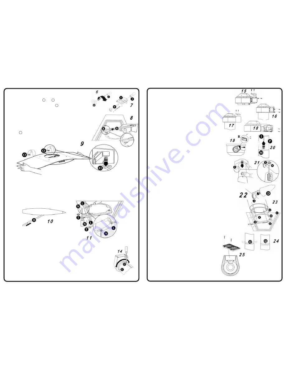
(b) The ducting fan unit air outlets must be arranged
according to the type of installation to be carried
out.
- Air outlet directed upwards (fig. 1a)
- Remove the plastic plug from the upper part of the
venting grill and replace it on the rear part (fig. 15).
- Air outlet directed towards the wall (fig. 1b).
- Remove the plastic frame from the air
outlet (fig. 16).
- Remove the plug from the upper part of
the ducting fan unit (fig. 17), as it is not
possible to insert the flange F with the
plug in place.
- Fit the flange F Ø150 mm (fig. 18),
replace the plug.
- Air outlet directed to the right or left hand
side (fig. 2a-b)
- Remove the four screws fastening the
plastic frame, as shown in fig. 16
- Fit the ducting spigot R (fig. 19) and
replace the four screws removed as above.
2-Fixing the chimney
(a) Loosen the screws M fixing the two parts of
the chimney and pull the inner section I (fig. 20)
almost all the way out. Remove the protective
film P.
(b) Rest the lower section of the chimney in its
housing on the top of the canopy. Lower the
ducting fan unit until it reaches the wall bracket S
and fix it using the screw H provided (fig. 21). Fit the
cover D (provided) on the wall bracket S (fig. 22).
(c) Insert gasket G1 (found in the accessory bag) on the
base of chimney stack A, so that it adheres perfectly
to the shape of chimney stack A. Then fix chimney
stack A to the hood unit C using four of the screws
provided E (fig. 23).
(d) Insert the transparent seal Q (provided), so as to
eliminate any play between the two parts of the
chimney (fig. 24). Lock the screws M (fig. 20).
(e) Remove the support rod B (fig. 10).
DUCTING OR RECIRCULATION FITTING
1-Ducting fitting.
This is possible for all forms of installation:
(a) Connect the air outlet to the external
ducting system.
(b) Remove the activated charcoal filter
(if there is one) inside the hood canopy
2-Recirculation fitting
This is only possible with the air outlet
directed upwards. Fit the venting grille G on
to the air outlet (fig. 25). The activated
charcoal filter should be fitted inside the
canopy after connection to the power supply.
104473 Issue B
ECN: 07 007
2-Fitting the fixing elements
(a) Insert the rawl plugs provided (or suitable anchors,
if required)into holes 1 and 2 .
(b) Fit the eye bolts O (Fig. 6).
(c) Fix the wall bracket S in hold 2 using the screw V
provided (fig. 7)
3-Fitting the canopy to the wall
(a) Remove the metal grease filter and the activated
charcoal filter, if there is any.
(b) Fit the support rod B using the two screws
provided K (fig.8).
(c) Hook the canopy to the eye bolts O fixed in
holes 1 (fig. 9).
(d) Adjust the support rod B so that it pushes against
the wall (fig. 10).
(e) Adjusting position (fig.11). There are two adjustable hooks at the rear of the hood,
which can be used to adjust its position as follows:
- Turn the screws L until the position of screws N coincides with the lower access
holes.
- Turn the screws N to adjust the vertical and horizontal position of the hood.
- Lock the screws L to fasten the hood against the wall.
- Insert the plugs T provided in the holes giving access to screws N.
INSTALLATION OF THE CHIMNEY
1-Direction and position of the ducting fan unit
(a) The hood is normally supplied with the air outlet directed towards
the wall, if it is to be installed with the air outlet directed to the
right or left, it will be necessary to change the direction of the
ducting fan unit, proceeding as follows:
- Unscrew the screws U (fig. 14)
- Turn the ducting fan unit 60o to the right or left;
- Replace the screws U.
- 5 -
- 4 -


