14
Mounting of the cross-cut table
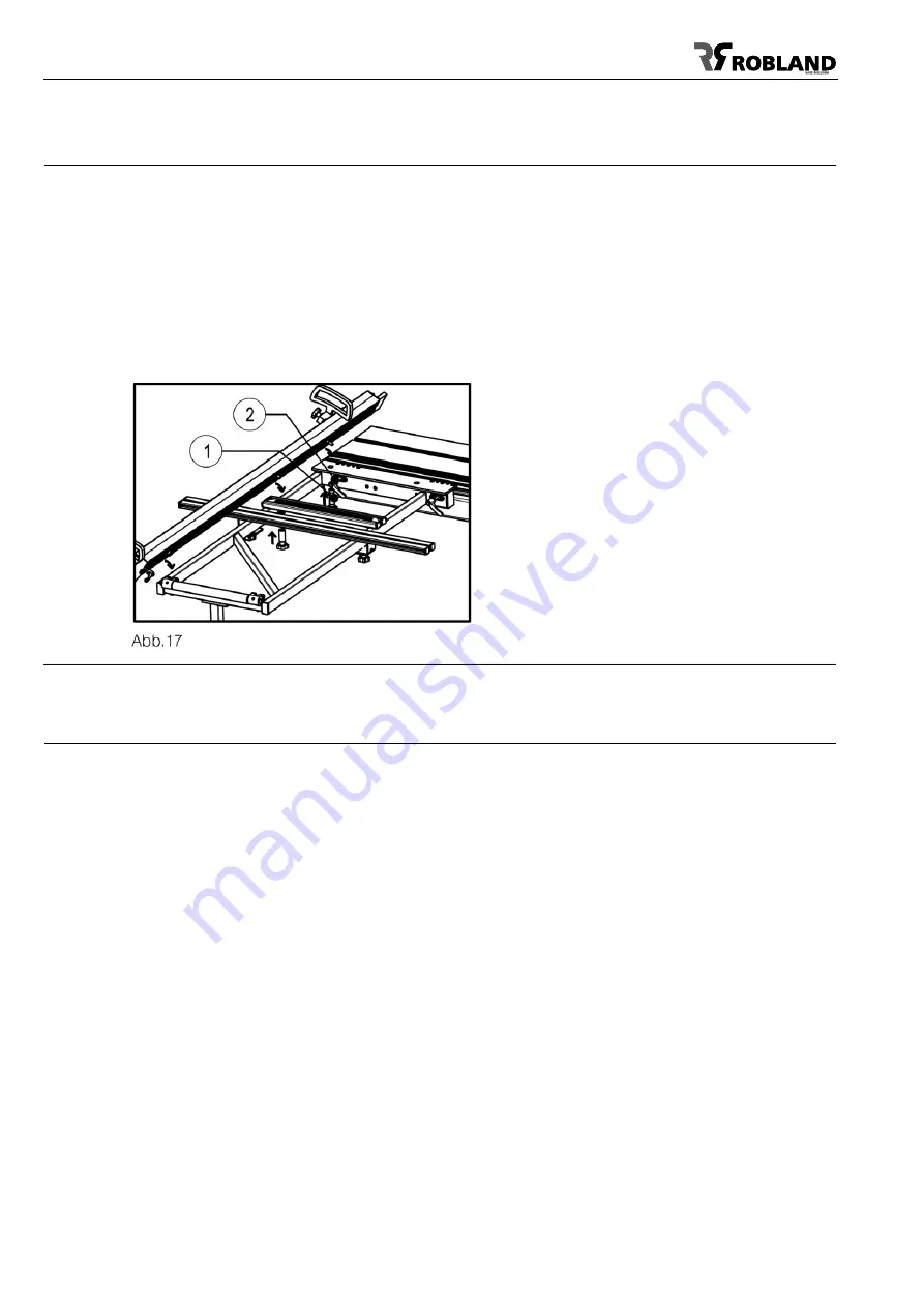
(Fig.17)
The cross-cut table can be mounted on the sliding table as follows: make sure that both mounting
brackets are well placed in the lateral groove of the sliding table.
The locking itself is done with the two locking handles (1). Make sure the cross-cut table rests well on
the vertical post of the telescopic arm. The machine serves only to put the cross-cut table at the back
of the sliding table, with a maximum at the centre.
The cross-cut table and fence are factory set at 90° to the saw blade but if for some reason this is not
the case and not exact anymore, the 90° angle setting adjustment is done by loosening the 4 bolts (2)
and shifting the complete cross-cut table. Make sure these 4 bolts are well tightened after the
adjustment is done. The cross-cut table can only be mounted at the end of the sliding table. To put it
more forwards (max. in the middle), use the optional longer telescopic tube.
Mounting of the cross-cut fence
(Fig.18A-B)
To place the cross-cut fence on the cross-cut table, place the fence with the right hinge pin (1) in the
fastening hole on the front of the table (fig. 18B). Now place the clamping screw (2). Slide the fence
backwards until the stop bolt (3) is securely in the rear support point (4) and the stop bolt (5) in the
support point. These support points also serve as a 90 ° stop. The support point (4) is set fixed but
can be adjusted if desired, but it does not serve to adjust the squareness of the fence, this is done with
4 adjusting bolts (fig 17, 2), but to adjust the rear fastening point without play. The fence can be used
in 2 positions at the front or the rear, and at an angle. All attachment points are factory-set.
There is an optional index system for the fence. This allows you to cut accurately at an angle and have
a correct length reading on the fence. Loosen the 3 clamping screws loosely, push the stop beam
forward so that it is free from the support point (4). Now the fence can be moved at an angle. The
angle can be read on the measuring scale (7). Now pull the fence backwards until the stop (5) falls
into one of the notches on the index plate (8). Now you are sure of angle and length. Now the
clamping screws (2 and 6) can be fixed again.
Summary of Contents for M500 EL
Page 6: ...6 General dimensions...


