–
English
–
Deutsch
NZ3200 - AXIS ERGO
V1110
9
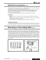
Electrical connection
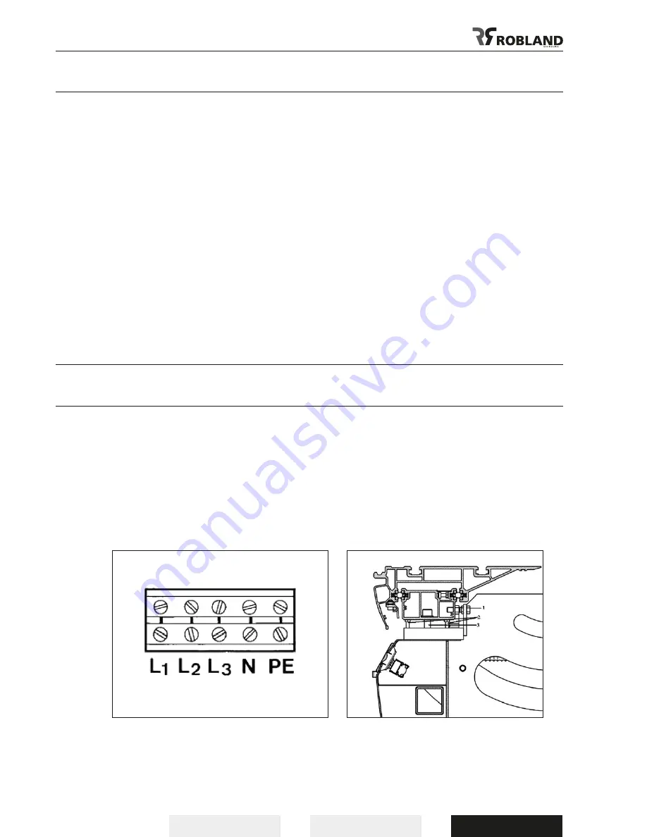
(Fig.3)
The electrical connection must be carried out by a qualified electrician who is able to calculate exactly
the required wire cross-section and capacity of the workshop fuses.
Check that the main voltage of the machine corresponds with the voltage supply to your workshop.
Now open the electrical switch panel and introduce the cable. Connect the 3 phases to the
terminals on the connection block marked L1, L2, L3. If there is a neutral conductor (blue)
it must be connected to the terminal N.
Connect the earth wire (green-yellow) to the terminal marked with the earth symbol PE.
ATTENTION :
- Check first if the saw spindle runs freely and if all safety devices are fitted before starting the
machine.
- If the direction of rotation of the sawblade is not correct, the wires L1 and L2 must be exchanged
(clockwise direction of the spindle is correct).
- For safety reasons this must only be done without the sawblade on the spindle !
THERMAL OVERLOADS
The machine has overload protections on both saw and scoring motors. Should the motor be shut-off
by one of these protectors, it is necessary to wait a few minutes untill the overload has cooled down.
Mounting on the sliding table
(Fig.4)
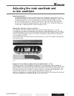
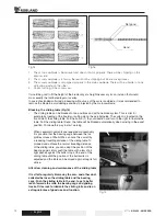
To obtain a good arrangement and function of the sliding table; it is vital that the machine is put on a
right level in both directions, with the help of a level, before putting the sliding table on the machine.
All the adjustments and arrangements are done in the factory. Simply put the table onto the frame with
the two lateral adjustment bolts (1) into the two lugs of the frame. Be sure that the girder rests well in
the height adjustment bolts. Now place the 4 big Allen bolts (3) and tighten well. In order to obtain a
good movement of the wood or the sliding table, the sliding table is set near to 2 mm above the sawing
table. The parallelism between the principal blade and the sliding table, can be corrected by using 2
bolts. After the adjustment, the 4 bolts need to be tightened well with a Torque wrench with a value of
7 kg. The adjustment in height of the sliding table can be done by using 8 bolts (2) but always with the
big bolts closed.
Fig.3
Fig.4
Summary of Contents for NZ 3200
Page 1: ...NZ 3200 NZ AXIS ERGO Manual Betriebsanleitung...
Page 3: ...English Deutsch 2 V1110 NZ3200 AXIS ERGO...
Page 32: ...English Deutsch NZ3200 AXIS ERGO V1110 31...
Page 60: ...English Deutsch NZ3200 AXIS ERGO V1110 59...
Page 61: ...English Deutsch 60 V1110 NZ3200 AXIS ERGO...
Page 62: ...English Deutsch NZ3200 AXIS ERGO V1110 61...
Page 63: ...English Deutsch 62 V1110 NZ3200 AXIS ERGO...
Page 64: ...English Deutsch NZ3200 AXIS ERGO V1110 63...
Page 65: ...English Deutsch 64 V1110 NZ3200 AXIS ERGO...
Page 66: ...English Deutsch NZ3200 AXIS ERGO V1110 65...
Page 67: ...English Deutsch 66 V1110 NZ3200 AXIS ERGO...
Page 68: ...English Deutsch NZ3200 AXIS ERGO V1110 67...
Page 69: ...English Deutsch 68 V1110 NZ3200 AXIS ERGO...
Page 70: ...English Deutsch NZ3200 AXIS ERGO V1110 69...
Page 71: ...English Deutsch 70 V1110 NZ3200 AXIS ERGO...
Page 72: ...English Deutsch NZ3200 AXIS ERGO V1110 71...
Page 73: ...English Deutsch 72 V1110 NZ3200 AXIS ERGO...
Page 74: ...English Deutsch NZ3200 AXIS ERGO V1110 73...
Page 75: ...English Deutsch 74 V1110 NZ3200 AXIS ERGO...
Page 76: ...English Deutsch NZ3200 AXIS ERGO V1110 75...
Page 77: ...English Deutsch 76 V1110 NZ3200 AXIS ERGO...
Page 78: ...English Deutsch NZ3200 AXIS ERGO V1110 77...
Page 79: ...English Deutsch 78 V1110 NZ3200 AXIS ERGO...
Page 80: ...English Deutsch NZ3200 AXIS ERGO V1110 79...


