EN
7
7
INSTALLATION
Wall drilling and bracket fixing
11a
1
1
2
2
210
11
12a
247 247
1004
482
400
210
X
1÷2
7.2.1
As a first step, proceed with the following drawings:
• a vertical line up to the ceiling or up to the upper limit, at the centre of the area in which the
hood is to be fitted;
• a horizontal line at a minimum 1004 mm above the cooker top.
• Mark a point
(1)
on the horizontal line, 247 mm to the right of the vertical reference line.
• Repeat this operation on the other side, checking that the two marks are levelled.
• Mark a reference point
(2)
as indicated at 210 mm from the vertical reference line and 482
mm above the cooker top.
• Repeat this operation on the other side, checking that the two marks are levelled.
• Drill at the marked points
(1)
, using a ø 12 mm drill bit.
• Drill at the marked points
(2)
using a ø 8 mm drill bit.
• Insert the bracket plugs
11a
into the holes (
1)
and tighten the screws.
• Insert plug
11
into holes
(2)
.
To install a decorative chimney ( optional )
• Place bracket
7.2.1
on the wall, about 1-2 mm from the ceiling or from the upper limit,
aligning the centre (notch) with the vertical reference line.
• Mark the wall at the centres of the bracket holes.
• Place the bracket
7.2.1
on the wall at X mm below the first bracket (X = height of the upper
chimney section), aligning the centre (notch) with the vertical line.
• Mark the wall at the centres of the bracket holes.
• Drill ø 8 mm holes at all the marked centre points.
• Insert the wall plugs
11
in the holes.
• Fix the brackets using the
12a
screws (4,2 x 44,4) supplied with the hood.
Summary of Contents for Creatix
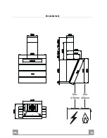
Page 6: ...EN 6 6 Dimensions Min 400mm Min 400mm...
Page 16: ...FR 1 16 Encombrement Min 400mm Min 400mm...
Page 26: ...DE 2 26 Platzbedarf Min 400mm Min 400mm...
Page 36: ...ES 3 36 Dimensiones Min 400mm Min 400mm...
Page 44: ...GR 4 44 650 mm I 120mm 0 04 mBar 2...
Page 46: ...GR 4 46 Min 400mm Min 400mm...
Page 48: ...GR 4 48 Vr 11a 11a Vr 12a 12a Vr 11a o150 120 mm o120 mm 9 150 9 120...
Page 49: ...GR 4 49 12c 2 9 x 6 5 8 2 12d 2 9 x 9 5 16 12c 12d 8 9 12r 12r...
Page 50: ...GR 5 50 3 mm 7 2 1 4 12c 2 9 x 9 5 2 12c 2 9 x 9 5 12c 2 1 2 2 2 7 2 1 12c 1...
Page 52: ...GR 5 52 1 5 V LR03 AAA Led 24H 2 F 24H 5...
Page 54: ...RU 5 54 650 I 120 0 04 2...
Page 56: ...RU 5 56 Min 400mm Min 400mm...
Page 58: ...RU 5 58 Vr 11a 2 11a Vr 12a 12a Vr 11a 150 120 120 9 150 9 120...
Page 59: ...RU 5 59 4 12c 2 9 x 6 5 8 2 12d 2 9 x 9 5 16 12c 12d 8 9 12r 12r...
Page 60: ...RU 6 60 3 7 2 1 4 12c 2 9 x 9 5 2 12c 2 9 x 9 5 12c 2 1 2 2 2 7 2 1 12c 1...
Page 62: ...RU 6 62 1 5 LR03 AAA 24H 2 F 24H 5...
Page 63: ...RU 6 63 24H 4 E 2 1 F 24H 5 1M EN 60825 1 1994 A1 2002 A2 2001 439nm 7...
Page 66: ...NL 6 66 Buitenafmetingen Min 400mm Min 400mm...
Page 74: ......
Page 75: ......
Page 76: ...991 0270 997_ver1...

