background image

9

GB

e-  Check the connectors of the motor (

Fig 9)

.

f-   Test the lights and the fan motor.

g-  Fit the metal grease filters and close the deflector.

IN THE RECIRCULATION MODE:

a-  To carry out an inlet  for recycling air in the kitchen (

Fig.11

).

b-  Connect the ducting 150mm (6 INS) not provided between motors 

item 6

 and the recirculation spigot 

and secure the connections with appropriate clamping rings or adhesive tape (

Fig. 12

).

c-  Make the electrical connection of the motor as described in the section titled ELECTRICAL.

d-  Place the canopy under the motor housing and fix it with the crews provided as illustrated in 

Fig. 10

.  

Attention:  2 persons are necessary to secure this operation.

e-  Connect the electrical plug of the motor cord on the body hood (

Fig.7

).

f-  Check the connectors of the motor (

Fig 9)

.

g-


Test the lights and the fan motor.

h- Fit the charcoal filter onto the inlets of the motor (

Fig. 13

).

i-  Fit the metal grease filters and close the deflector.

• CLIPPAGE ON THE FALSE CEILING

2) Mark the centre of the cooking appliance onto the ceiling with a plumb line. Draw the horizontal axes

running parallel to the stove top onto the ceiling as illustrated 

Fig. 1

.

3) To carry out the cutting of embedding in the suspended ceiling (

Fig 2a

).

4) To remove the lighting front panel (

Fig. 15

).

5) To unscrew the screws of the clips according to the thickness of the false ceiling (

Fig. 16

). When fixing

the cooker hood to a plasterboard ceiling ensure it is reinforced as illustrated in 

Fig. 17. 

For the false 

ceiling in MDF of 18 mm, 4 holds of compensation (2 

m

m thickness) are provided with the hood.

6) Open the deflector ( 

Fig. 6 Rep. 12) 

by pushing / unlocking (

Fig. 14

).

7) To remove the metal filters.

IN THE EXTRACTION MODE:

a-  Fit the non-return backflow flaps 

over the round outlet 

item 6

 on top of the canopy while pressing 

down until they snap into position, and then connect the ducting 150mm (6 INS) and secure the connec-

tions with appropriate clamping rings or adhesive tape (

Fig. 8

).

b-  Make the electrical connection of the motor as described in the section titled ELECTRICAL.

c-  Place the canopy under the motor housing and fix it with the screws provided as illustrated in 

Fig. 10


or clip the hood on the false ceiling (

Fig. 15

), to tighten the screws (

Fig. 16

) and to fit back the lighing 

front panel.  

Attention:  2 persons are necessary to secure this operation.

.

d-  Connect the electrical plug of the motor cord on the body hood (

Fig.7

).

e-  Check the connectors of the motor (

Fig 9)

.

f-   Test the lights and the fan motor.

g-  Fit the metal grease filters and close the deflector.

IN THE RECIRCULATION MODE:

a-  To carry out an inlet  for recycling air in the kitchen (

Fig.11

).

b-  Connect the ducting 150mm (6 INS) not provided between motors 

item 6

 and the recirculation spigot 

and secure the connections with appropriate clamping rings or adhesive tape (

Fig. 12

).

c-  Make the electrical connection of the motor as described in the section titled ELECTRICAL.

d-  Place the canopy under the motor housing and fix it with the screws provided as illustrated in 

Fig. 10


or clip the hood on the false ceiling (

Fig. 15

), to tighten the screws (

Fig. 16

) and to fit back the lighing 

front panel.   

Attention:  2 persons are necessary to secure this operation.

e-  Connect the electrical plug of the motor cord on the body hood (

Fig.7

).

f-  Check the connectors of the motor (

Fig 9)

.

g-


Test the lights and the fan motor.

h- Fit the charcoal filter onto the inlets of the motor (

Fig. 13

).

i-  Fit the metal grease filters and close the deflector.

Summary of Contents for Inspiration 4 FX 1000

Page 1: ...Inspiration 4 FX 1000 1400 FR GB Mode d emploi et installation Hotte de Cuisine Instructions for use and installation Cooker Hood...

Page 2: ...POSE DE L APPAREIL FONCTIONNEMENT CONSEILS D UTILISATIONS ENTRETIEN GARANTIE ET SERVICE APR S VENTE REMARQUES GB CONTENTS ELECTRICAL WIRING INSTALLATION ADVICE FITTING THE APPLIANCE OPERATION USEFUL H...

Page 3: ...ct de 3 mm doit tre install avant la hotte Le fil de terre Jaune vert ne doit pas tre interrompu par cet interrupteur 2 CONSEILS D INSTALLATION Nous vous conseillons une hauteur de pose maximale de 1...

Page 4: ...fond est en b ton employer 4 chevilles en fonte pour 10 exclure les chevilles en plastique Si celui ci vous semble de solidit douteuse n h sitez pas le renforcer dans les combles Fig 3 Fixer solidemen...

Page 5: ...le l aide de colliers ou de ruban adh sif appropri s Fig 8 b Raccorder lectriquement le moteur Voir paragraphe Raccordement Electrique c Fixer le corps de la hotte Fig 10 ou clips l appareil sur le fa...

Page 6: ...s qu moteur teint Affiche 24 et le point en bas droite cli gnote tandis que le moteur est en service Une fois la proc dure termin e la signalisa tion visualis e en pr c dence s teint FF signale la n c...

Page 7: ...de l air Conduit d vacuation V rifier tous les 6 mois le bon coulement de l air vici Observer les prescriptions r glementaires locales concernant l vacuation de l air vici clairage Avant toute interve...

Page 8: ...llez vous informer du syst me local de s paration des d chets lectriques et lectroniques Veuillez agir selon les r gles locales et ne pas jeter vos produits usag s avec les d chets domestiques usuels...

Page 9: ...the underside of the cooker hood and the cooker hood should be positioned away from doors and windows which will create turbulence Ducting If the room where the hood is to be used contains a fuel bur...

Page 10: ...erboard ceiling ensure it is reinforced as illustrated in Fig 3 and attach using four 10mm nuts and bolts ensuring the bolts as sleeved between the plasterboard and the joist supports to prevent the c...

Page 11: ...g Fig 14 7 To remove the metal filters IN THE EXTRACTION MODE a Fit the non return backflow flaps C over the round outlet item 6 on top of the canopy while pressing down until they snap into position...

Page 12: ...ications are only visible when the motor is turned off Displays 24 and the bottom right hand spot flashes while the motor is turned on On completing the procedure the previous indicator is turned off...

Page 13: ...ove the metal grease filters one at a time by releasing the catches on the filters the filters can now be removed The metal grease filters should be washed by hand in mild soapy water or in a dishwash...

Page 14: ...parts of glass or plastic These items are considered to be consumable under the terms of this guarantee 8 REMARKS This appliance complies with European regulations on low voltages Directive 2006 95 C...

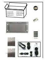
Page 15: ...Composants Components Bauelemente Componenti Componentes Onderdelen 2 mm 2 LR03 AAA 1 5V 1 3...

Page 16: ...Connection Unit to BS 1363 Part 4 fitted with a 3 Amp fuse is a recommended mains supply connectionaccessoryto ensure compliance with the Safety Requirements applicable to fixed wiring instructions Th...

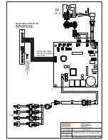
Page 17: ...R COMMANDE PUSCH BUTTON PANEL MULTI FLACH KABEL LIMANDE COMMANDE FLAT CABLE 4x 5W Maj Update D signation 01 01 2015 INSPIRATION 4 FX 1000 1400 Page 1 1 3S_INSPIRATION FX 4_1000 1400_150101 FERNBEDIENU...

Page 18: ...Sans Moteur 450 240 960 1360 460 560 100 31 44 343 342 1 9 6 153 5 188 5 955 1355 1000 1400 451 551 500 600...

Page 19: ...1400 1000 100 299 20 0 402 371 5 270 342 36 201 1 5 4 1 5 5 0 0 5 0 0 6 5 5 9 5 5 3 1 149 20 0 90 180 270 450 240 0 6 9 0 6 3 1 0 6 4 0 6 5...

Page 20: ...1 2a 960 1360 mm 2b 460 560 mm 450 240 0 6 9 0 6 3 1 0 6 4 0 6 5...

Page 21: ......

Page 22: ...3 4 371 5 270 342 36 0 90 180 270...

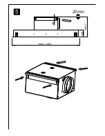
Page 23: ...5 1400 1000 100 299 20 0 20 20 mm...

Page 24: ...6 12 7...

Page 25: ...8 6 C 371 5 270 342 36 0 90 180 270...

Page 26: ...9 10...

Page 27: ...11 6 12 13...

Page 28: ...14...

Page 29: ...15...

Page 30: ...16 Min 20 mm Max 35 mm Faux plafond platre False ceiling plaster Faux plafond MDF False ceiling MDF Cadre Renforcement Frame Reinforcement 18 mm Cale Spacer 17...

Page 31: ...2 x 5 W 2 x 5 W B A C D E F...

Page 32: ...er Dunstesse Etichetta all interno della cappa Etiqueta de la campana Typeplaatje van de afzuigkap R glage serrage charni re Adjustment tightening hinge Einstellung Scharnierfestklemmen Regalazione ce...

Page 33: ...A S 25 Rue des Rosiers Sainte C cile B P 60056 50800 VILLEDIEU LES PO LES France T l 02 33 91 26 50 Fax 02 33 51 54 79 e mail com france roblin fr For outside France Tel 33 0 2 33 91 26 57 Fax 33 0 2...

Reviews: