7
GB
markings identifying the terminals in your plug, proceed as follows.
- The wire which is coloured green and yellow must be connected to the terminal in the plug which is
marked with the letter
E
or by the earth symbol or coloured green or green and yellow.
- The wire which is coloured blue must be connected to the terminal which is marked with the letter
N
or
coloured black.
- The wire which is coloured brown must be connected to the terminal which is marked with the letter
L
or
coloured red.
ATTENTION: Do not forget to use adequate plugs to the support brackets. Enquire after the
manufacturers. Do an embedding if necessary. The manufacturer accepts no responsibility in
case of a faulty hanging due to the drilling and the setting up of plugs.
GB
1 - Remove the self-tapping screws, which fix the chimney to the metal frame as illustrated in fig. 5.
2 - Remove the eight 5 x 10T hexagon screws, which fix the frame to the metal diffuser as illustrated in
fig. 1a.
3 - Mark the positions on the ceiling for the cut-out for the ducting, the mains supply cord and the fixing
holes as illustrated in fig. 2a .
When fixing the cooker hood to a plasterboard ceiling ensure it is reinforced as illustrated in fig. 3 and
attach using four Ø10mm nuts and bolts; ensuring the bolts as sleeved between the plasterboard and
the joist supports to prevent the ceiling being damaged when the bolts are tightened up.
If the ceiling is concrete, use four Ø10mm steel rawl bolts. Plastic rawl plugs must not be
used.
4 - The height of the cooker hood can be adjusted in 50mm stages. Select the height required using the
measurements illustrated in fig. 1a and fix the metal diffuser to the frame using the eight 5 x 10T hexa
-
gon headed screws. A spot of coloured paint on the diffuser defines the positioning for the controls.
5 - Connect the flexible ducting through the hole in the ceiling to the spigot on the top of the diffuser
and fix the ducting using the screws provided.
RECYCLING
1 - When installing the hood in the recycling version it is necessary to fit the deflector as illustrated in fig.
5.
2 - Position the deflector inside the frame and ensure the outlets align with the grilles on each side of the
chimney. Fix the deflector using the M4 x 12 screws provided as illustrated in fig. 5.
3 - Connect a short length of flexible ducting to the top of the diffuser and the underside of the deflector.
4 - Remove the grease filter cassettes and fix the charcoal filter retaining bracket onto the underside of
the casing using the two 4.2 x 9.5mm self tapping screws provided as illustrated in fig. 6 ensuring the
bracket is fitted with the screws to the fore.
5 - Insert the charcoal filter and secure by inserting the clips on the filter into the holes in the retaining
bracket as illustrated in fig. 6.
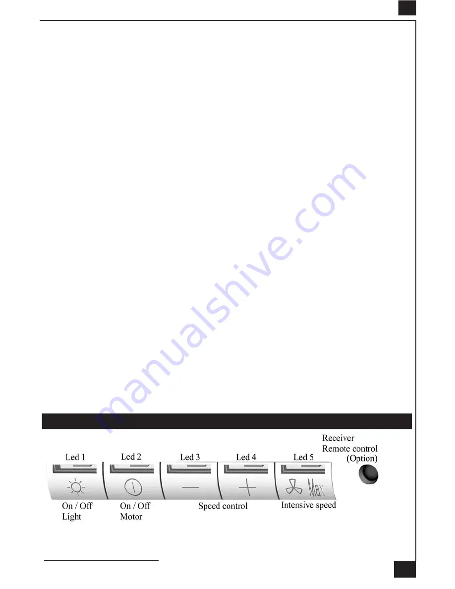
4 OPERATION
A - EXTRACTION OR RECYCLING :
Your cooker hood is supplied in the extraction mode. To use the cooker
hood in the recycling mode re-programme the hood as follows:
Starting in the recycling mode
(the contaminated air passes into the hood through the grease filters and
Summary of Contents for LINEAR CENTRALE
Page 37: ... 1a 2a 3 4 770 820 870 920 970 ...
Page 38: ...3 5 6 ...
Page 40: ...38 A B C D E F F ...
Page 41: ...39 G H I J K L ...
Page 43: ...41 Composants Components Bauelemente Componenti Componentes Onderdelen 5 5 7a 7a 7b 7b 2 8 ...


