background image


EN 

5


INSTALLATION


Drilling the Support surface and Fitting the Hood 

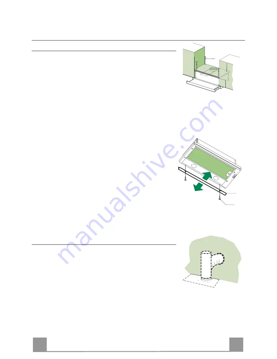
SCREW FITTING 

•  The hood support surface must be 135 mm above the bottom 

surface of the wall units. 

•  Drill the support with a ø 4,5 mm drill bit, using the drilling 

template provided. 

•  Cut a hole  ø 150 mm in size on the support surface, using the 

drilling template provided. 

•  Fix using the 4 screws 

12a

 (4,2 x 44,4) provided. 


12a

135

150

CLOSING ELEMENT 

•  The space between the edge of the hood and the rear wall can 

be closed by applying the element 

20 

provided, using the 

screws 

12b


20

12b

Connections 

DUCTED VERSION AIR EXHAUST SYSTEM 

When installing the ducted version, connect the hood to the 
chimney using either a flexible or rigid 
pipe ø 150 mm, the choice of which is left to the installer. 
 
•  Fix the pipe in position using sufficient pipe 
  clamps (not supplied). 
•  Remove any activated charcoal filters. 


ø 150

Summary of Contents for Tiroir 612

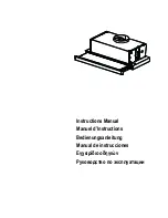
Page 1: ...Instructions Manual Manuel d Instructions Bedienungsanleitung Manual de instrucciones Εγχειρίδιο οδηγιών Руководство по эксплуатации ...

Page 2: ... INHALTSVERZEICHNIS EMPFEHLUNGEN UND HINWEISE 15 CHARAKTERISTIKEN 16 MONTAGE 17 BEDIENUNG 19 WARTUNG 20 INDICE CONSEJOS Y SUGERENCIAS 21 CARACTERÍSTICAS 22 INSTALACIÓN 23 USO 25 MANTENIMIENTO 26 ΠΕΡΙΕΧΟΜΕΝΑ ΣΥΜΒΟΥΛΕΣ ΚΑΙ ΣΥΣΤΑΣΕΙΣ 27 ΧΑΡΑΚΤΗΡΙΣΤΙΚΑ 28 ΕΓΚΑΤΑΣΤΑΣΗ 29 ΧΡΗΣΗ 31 ΣΥΝΤΗΡΗΣΗ 32 УКАЗАТЕЛЬ СОВЕТЫ И РЕКОМЕНДАЦИИ 33 ХАРАКТЕРИСТИКИ 34 УСТАНОВКА 35 ЭКСПЛУАТАЦИЯ 37 УХОД 38 EN FR DE ES GR RU ...

Page 3: ...llationforthegashobspecifyagreaterdistancespecifiedabove thishas tobetakenintoaccount Regulationsconcerningthedischargeofairhavetobefulfilled USE Theextractorhoodhasbeendesignedexclusivelyfordomesticusetoeliminatekitchensmells Neverusethehoodforpurposesotherthanforwhichithasbeendesigned Neverleavehighnakedflamesunderthehoodwhenitisinoperation Adjust the flame intensity to direct it onto the bottom...

Page 4: ... Components 1 1 Hood Body complete with Controls Light Blower Filters 8 1 Directional Air Outlet grille 20 1 Closing element Ref Q ty Installation Components 12a 4 Screws 4 2 x 44 4 12b 2 Screws 4 2 x 12 7 12e 2 Screws 2 9 x 9 5 Q ty Documentation 1 Instruction Manual 12b ...

Page 5: ...ovided Fix using the 4 screws 12a 4 2 x 44 4 provided 12a 135 150 CLOSING ELEMENT The space between the edge of the hood and the rear wall can be closed by applying the element 20 provided using the screws 12b 20 12b Connections DUCTED VERSION AIR EXHAUST SYSTEM When installing the ducted version connect the hood to the chimney using either a flexible or rigid pipe ø 150 mm the choice of which is ...

Page 6: ...n using sufficient pipe clamps not supplied Fix the directional grille 8 on the recirculation air outlet using the 2 screws 12e 2 9 x 9 5 provided Ensure that the activated charcoal filters have been inserted ø150 8 12e ELECTRICAL CONNECTION Connect the hood to the mains through a two pole switch having a contact gap of at least 3 mm When opening the sliding carriage for the first time after insta...

Page 7: ... given the optimum treated air flow noise level ratio 3 Maximum speed used for eliminating the highest cooking vapour emission including long periods L Light Switches the lighting system on and off M Motor Switches the extractor motor on and off V Speed Sets the operating speed of the extractor 1 Low speed used for a continuous and silent air change in the presence of light cooking vapour 2 Medium...

Page 8: ...e is visible on the outside Close the sliding suction panel Charcoal filter Recycling version REPLACING CHARCOAL FILTERS Warning Turn the lights off and wait until the lamps cool down before you change the odour filter These filters are not washable and cannot be regenerated and must be replaced approximately every four months or more frequently by particularly heavy use Pull out the sliding sucti...

Page 9: ...cernantl évacuationd airdoiventêtreremplies UTILISATION Lahotteaétéconçueexclusivementpourl usagedomestique danslebutd éliminerlesodeursdelacuisine Nejamaisutiliserabusivementlahotte Nepaslaisserlesflammeslibresàforteintensitéquandlahotteestenservice Toujoursréglerlesflammesdemanièreàévitertoutesortielatéraledecesdernièresparrapportaufonddes marmites Contrôlerlesfriteuseslorsdel utilisationcarl hu...

Page 10: ...oduit 1 1 Corps Hotte équipé de Commandes Lumière Groupe Ventilateur Filtres 8 1 Grille orientée Sortie de l Air 20 1 Profil fermeture Réf Q té Composants pour l installation 12a 4 Vis 4 2 x 44 4 12b 2 Vis 4 2 x 12 7 12e 2 Vis 2 9 x 9 5 Q té Documentation 1 Manuel d instructions 12b ...

Page 11: ...ec l appareil Fixer à l aide des 4 Vis 12a 4 2 x 44 4 fournies avec l appareil 12a 135 150 PROFIL DE FERMETURE Il est possible de boucher l espace entre le rebord de la Hotte et la Paroi du fond en appliquant le Profil 20 fourni avec l appareil avec les Vis 12b 20 12b Branchements SORTIE AIR VERSION ASPIRANTE En cas d installation en version aspirante brancher la hotte à la tuyauterie de sortie vi...

Page 12: ... matériau nécessaire n est pas fourni Fixer la Grille orientée 8 sur la sortie de l air recyclé à l aide de 2 Vis 12e 2 9 x 9 5 fournies avec l appareil S assurer de la présence des filtres anti odeur au charbon actif ø150 8 12e BRANCHEMENT ELECTRIQUE Brancher la hotte sur le secteur en interposant un interrupteur bipolaire avec ouverture des contacts d au moins 3 mm Après avoir installé la hotte ...

Page 13: ...ort optimal entre débit d air traité et niveau sonore 3 Vitesse maximum pour faire face aux émissions maximum de vapeur de cuisson même pendant des temps prolongés L Lumières Allume et éteint l éclairage M Moteur Allume et éteint le moteur aspiration V Vitesses Détermine les vitesses d exploitation ainsi subdivi sées 1 Vitesse minimale pour un rechange d air perma nent particulièrement si lencieux...

Page 14: ...artie visible externe Fermer le tiroir aspirant Filtres anti odeur Version Recyclage REMPLACEMENT Attention Éteindre les lumières et attendre le refroidissement des ampoules avant de procéder au remplacement du filtre anti odeur Les filtres ne peuvent pas être lavés ni régénérés il faut les remplacer tous les 3 4 mois d emploi environ ou bien plus souvent en cas d emploi particulièrement intense S...

Page 15: ...stausschließlichzumEinsatzimprivatenHaushaltundzurBeseitigungvonKüchen gerüchenvorgesehen UnsachgemäßerEinsatzderHaubeistzuunterlassen GroßeFlammenbeieingeschalteterHaubeniemalsunbedecktlassen DieIntensivitätderFlammeistsozuregulieren dasssiedenTopfbodennichtüberragt FrittiergerätemüssenwährenddesGebrauchsstetsbeaufsichtigtwerden überhitztesÖlkannsichentzünden KeineflambiertenSpeisenunterderAbzugs...

Page 16: ...omponenten 1 1 Haubenkörper mit Schaltern Beleuchtung Gebläsegruppe Filter 8 1 Luftleitgitter Luftaustritt 20 1 Abdeckprofil Pos St Montagekomponenten 12a 4 Schrauben 4 2 x 44 4 12b 2 Schrauben 4 2 x 12 7 12e 2 Schrauben 2 9 x 9 5 St Dokumentation 1 Bedienungsanleitung 12b ...

Page 17: ...rten Schrauben 12a 4 2 x 44 4 fixieren 12a 135 150 ABDECKPROFIL Der Bereich zwischen Haubenkante und Rückwand kann mit Hilfe des mitgelieferten Abdeckprofils 20 und der für diesen Zweck vorgesehenen Schrauben geschlossen werden 12b 20 12b Anschlüsse ANSCHLUSS IN ABLUFTVERSION Bei Abluftbetrieb kann die Haube vom Installateur wahlweise mittels Rohr oder Schlauch ø 150 mm an die Außenrohrleitung ang...

Page 18: ...Material wird nicht mitgeliefert Das Luftleitgitter 8 mit Hilfe von 2 der mitgelieferten Schrauben 12e 2 9 x 9 5 beim Austritt der rückzu führenden Luft fixieren Sicherstellen dass der Aktivkohle Geruchsfilter vor handen ist ø150 8 12e ELEKTROANSCHLUSS Bei Anschluss der Haube an das Stromnetz muss ein zweipoliger Schalter mit einem Öff nungsweg von mindestens 3 mm zwischengeschaltet werden Nach Mo...

Page 19: ...räuschentwicklung für die meisten Anwendungs situationen 3 höchste Gebläsestufe eignet sich für starke Kochdunstentwicklung auch über längere zeithin L Beleucht Schaltet die Beleuchtung ein und aus M Motor Schaltet den Gebläsemotor ein und aus V Geschw bestimmt die Gebläsegech windigkeit und steuert fol gende Geschwindigkeitsstu fen 1 geringste Gebläsestufe diese Stufe ist für einen ständigen und ...

Page 20: ...wieder einsetzen dabei darauf achten dass die Ver riegelung sichtbar ist Den Wrasenleitschirm wieder einschieben Aktivkohlefilter Umluftbetrieb FILTERWECHSEL Achtung Die Beleuchtung ausschalten und warten bis die Lam pe abgekühlt ist bevor der Geruchsfilter ausgewechselt wird Die Filter lassen sich nicht reinigen oder regenerieren und müssen spätestens nach vier Monaten Betriebszeit oder bei be so...

Page 21: ...asencuenta Esnecesariorespe tartodaslasnormativasrelativasalconductodedescargadelaire USO Lacampanahasidoconcebidaexclusivamenteparaunusodoméstico paraeliminarlosoloresdela cocina Noutilizarlademanerainadecuada Nodejarllamaslibresdefuerteintensidadmientraslacampanaestéfuncionando Regularsiemprelasllamasdemaneraqueéstasnosobresalganlateralmenteconrespectoalfondo delasollas Controlarlasfreídorasdura...

Page 22: ...uerpo campana dotado con mandos luz grupo de ventila ción filtros 8 1 Rejilla de dirección de salida del aire 20 1 Perfil de cierre Ref Cant Componentes de instalación 12a 4 Tornillos 4 2 x 44 4 12b 2 Tornillos 4 2 x 12 7 12e 2 Tornillos 2 9 x 12 7 Cant Documentación 1 Manual de instrucciones 12b ...

Page 23: ...de perforación suministrada en dotación Fijar con los 4 tornillos 12a 4 2 x 44 4 en dotación 12a 135 150 PERFIL DE CIERRE El espacio entre el borde de la campana y la pared de fondo se puede cerrar aplicando el perfil 20 en dotación con los tornillos 12b 20 12b Conexiones SALIDA DEL AIRE VERSIÓN ASPIRANTE Para la instalación de la versión aspirante conectar la campana al tubo de salida mediante un...

Page 24: ... rial no se proporciona en dotación Fijar la rejilla de dirección 8 en la salida del aire reci clado mediante los 2 tornillos 12e 2 9 x 9 5 en do tación Controlar que estén presentes los Filtros Antiolor al Carbón activo ø150 8 12e CONEXIÓN ELÉCTRICA Conectar la campana a la red de alimentación eléctrica instalando un interruptor bipolar con apertura de los contactos de 3 mm como mínimo Tras insta...

Page 25: ...e cau dal de aire tratado y nivel de ruido 3 Velocidad máxima indi cada para hacer frente a grandes cantidades de vapor de cocción incluso para tiempos prolongados L Luces Enciende y apaga la instala ción de iluminación M Motor Enciende y apaga el motor de aspiración V Velocidad Determina las velocidades de ejercicio 1 Velocidad mínima indica da para un recambio de aire continuo muy silencioso en ...

Page 26: ...ante SUSTITUCIÓN Atención Apagar las luces y esperar el enfriamiento de las lámparas antes de efectuar la sustitución del filtro antiolor No se puede lavar ni regenerar se debe cambiar cada 4 meses aproxi madamente La señal de alarma se produce solo cuando el motor de aspiración está funcionando Abrir el carro aspirante Quitar los filtros antigrasa metálicos Quitar el filtro antiolor de carbón act...

Page 27: ...ςκανονισμούςαναφορικάμετηνεκκένωσητουαέρα ΧΡΗΣΗ Ο απορροφητήρας έχει μελετηθεί αποκλειστικά για οικιακή χρήση και για την απαγωγή των οσμών τηςκουζίνας Μηχρησιμοποιείτεποτέ γιαάλλεςχρήσειςτοναπορροφητήρα Μηναφήνετεελεύθερεςφλόγεςμεγάληςέντασηςκάτωαπότοναπορροφητήραότανλειτουργεί Ρυθμίζετεπάντατιςφλόγεςέτσιώστεναμηνπροεξέχουνπολύαπότονπάτοτωνσκευών Ελέγχετετιςφριτέζεςότανχρησιμοποιούνται τοκαυτόλάδ...

Page 28: ... Σώμα Απορροφητήρα συμπληρώνεται από τον Πίνακα Ελέγχου το Φωτισμό τον Ανεμιστήρα τα Φίλτρα 8 1 Γρίλια Οδήγησης Αέρα Εξόδου 20 1 Στοιχείο κλεισίματος Αναφ Ποσοτ Εξαρτήματα Προϊόντος 12a 4 Βίδες 4 2 x 44 4 12b 2 Βίδες 4 2 x 12 7 12e 2 Βίδες 2 9 x 9 5 Ποσοτ Τεκμηρίωση 1 Gebruiksaanwijzing 12b ...

Page 29: ...τος που παρέχεται Στερεώστε χρησιμοποιώντας τις 4 βίδες 12a 4 2 x 44 4 που παρέχονται 12a 135 150 ΣΤΟΙΧΕΙΟ ΚΛΕΙΣΙΜΑΤΟΣ Ο χώρος μεταξύ της άκρης του απορροφητήρα και του πίσω τοίχου μπορεί να καλυφθεί εφαρμόζοντας το στοιχείο 20 που παρέχεται με τις βίδες 12b 20 12b Συνδέσεις ΕΞΟΔΟΣ ΑΕΡΑ ΜΟΝΤΕΛΟΥ ΑΠΑΓΩΓΗΣ Για την εγκατάσταση του μοντέλου απαγωγής συνδέστε τον απορρο φητήρα στο σωλήνα εξόδου με έναν...

Page 30: ...υ χρησιμοποιώντας σφιγκτήρα σωλήνων δεν παρέχεται Στερεώστε τις γρίλιες οδηγούς 8 στην έξοδο επανακυ κλο φορίας αέρα χρησιμοποιώντας τις 2 βίδες 12e 2 9 x 9 5 που παρέχονται Σιγουρευτείτε ότι φίλτρα ενεργού άνθρακα έχουν τοπο θετηθεί ø150 8 12e ΗΛΕΚΤΡΙΚΗ ΣΥΝΔΕΣΗ Συνδέστε τον απορροφητήρα στην κεντρική παροχή τροφοδοσίας διαμέσου ενός διπολικού διακόπτη που έχει ένα κενό επαφών τουλάχιστον 3 χιλιοσ...

Page 31: ...ιστη αναλογία ροής αέρα στάθμη θορύβου 3 Μέγιστη ταχύτητα χρησιμοποιείται για να απομακρύνει έντονες οσμές μαγειρέματος συμπεριλαμβανομένου μεγάλων χρονικών διαστημάτων L Φωτισμός Ανάβει και σβήνει το φωτισμό M Μοτέρ Ενεργοποιεί και απενεργοποιεί το μοτέρ V Ταχύτητα Ρυθμίζει την ταχύτητα λειτουργίας του απορροφητήρα 1 Χαμηλή ταχύτητα χρησιμο ποιείται για συνεχής και ήσυχη εναλλαγή αέρα όταν υπάρχο...

Page 32: ... το συρόμενο τμήμα αναρρόφησης Φίλτρα ενεργού άνθρακα Μοντέλο ανακύκλωσης ΑΝΤΙΚΑΤΑΣΤΑΣΗ Προσοχή Σβήστε τα φώτα και περιμένετε μέχρι να κρυώσουν οι λαμπτήρες πριν αντικαταστήσετε το φίλτρο ενεργού άνθρακα Δεν μπορούν να πλυθούν και να αναγεννηθούν και πρέπει να αντικαθίστανται περίπου κάθε 4 μήνες χρήσης ή συχνότερα σε περίπτωση ιδιαίτερα συχνής χρήσης Βγάλτε το συρόμενο τμήμα αναρρόφησης Βγάλτε τα...

Page 33: ... ЭКСПЛУАТАЦИЯ Вытяжкаспроектированаисключительнодлябытовогоприменениядляуничтожениязапаховотготовки Никогданедопускатьнесоответствующегопользованиявытяжкой Неоставлятьоткрытоеисильноепламяподнаходящейсявработевытяжкой Обязательнорегулироватьпламя чтобыононевыходилозаднокастрюль Следитьзаработойфритюрниц сильнонагретоемасломожетвоспламениться Неготовьтеблюдафламбеподкухоннойвытяжкой опасностьвозник...

Page 34: ...ус вытяжки в комплекте с устройствами управления ос вещением вентилятором фильтрами 8 1 Регулируемая решетка выпуска воздуха 20 1 Затворный профиль Об Кол Установочные элементы 12a 4 Винты 4 2 x 44 4 12b 2 Винты 4 2 x 12 7 12e 2 Винты 2 9 x 9 5 Кол Документы 1 Руководство по 12b ...

Page 35: ...в комплект 4 винтами 12a 4 2 x 44 4 12a 135 150 ЗАТВОРНЫЙ ПРОФИЛЬ Пространство между краем вытяжки и задней стеной мо жет быть закрыто прилагаемым в комплекте профилем 20 и соответствующими винтами 12b 20 12b Соединения ВЫПУСК ВОЗДУХА ИЗ ВСАСЫВАЮЩЕЙ ВЫТЯЖКИ Для установки всасывающей вытяжки соединить ее с выпу скной трубой жесткой или гибкой трубкой диаметром 150 мм тип которой может выбрать монта...

Page 36: ...ого материал не входит в комплект поставки Закрепить решетку 8 на выпускном отверстии 2 винтами 12e 2 9 x 9 5 прилагаются Проверить наличие в вытяжке фильтров от запа хов на активном угле ø150 8 12e ЭЛЕКТРИЧЕСКОЕ ПОДКЛЮЧЕНИЕ Подключить вытяжку к сети питания через двухполюсный выключатель с минималь ным разведением контактов в 3 мм После установки вытяжки необходимо в первый раз энергично открыть ...

Page 37: ...я способность обработанного воздуха и уровень шума 3 Максимальная скорость пригодна для обработки наибольших испарений от готовки даже в течение длительного времени L Освещение Включает и выключает осве тительное оборудование M Мотор Включает и выключает мотор всасывания V Скорость Регулирует рабочую скорость 1 Минимальная скорость пригодна для непрерывной смены воздуха при наличии малого количест...

Page 38: ...ающую каретку Фильтрыпротивзапахов фильтрующаявытяжка ЗАМЕНА Внимание выключите свет и подождите пока не остынут лампоч ки прежде чем приступать к замене фильтра против запахов Эти фильтры нельзя мыть и восстанавливать Их следует заме нять приблизительно каждые 4 месяца работы или чаще в случае особенно интенсивного использования Вынуть всасывающую каретку Вынуть противожировые фильтры Вынуть филь...

Page 39: ......

Page 40: ...436005904_ver2 ...

Reviews: