background image

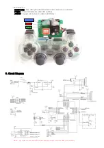
③ LED Indication

BLUETOOTH : Blue LED lights when Bluetooth communication is connected.
POWER : Power ON Indication (Red LED lighting)
JOYPAD : Joypad communication (Green LED blinks)

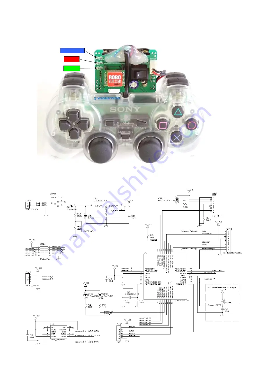
5. Circuit Diagram

※ NOTE : U3, CN6 is for acceleration sensor expansion part, and this does not included.

BLUETOOTH

POWER

JOYPAD

Summary of Contents for RBX-BTCONT-01

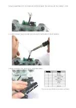
Page 1: ...not included in Part List Original Sony Playstation 2 Joypad is strongly recommended Some other Joypad works however we do not gurantee with other Joypad 2 RoboBuilder does not take any responsibility of physical injuries or damages during assembling 3 Installation Required parts SONY PlayStation 2 Joypad 1 EA AAA Battery 4 EA Bluetooth Kit RBX BLTOOTHCOM 1 EA Unscrew the bolt as shown in the belo...

Page 2: ... order to make it easy to solder put some lead on each edge of lines in advance Check out each pin No and color by using Multi meter The color can be different in accordance with parts Green 8 9 Color Brown Orange Grey or Purple Black Red or Pink Yellow Blue 4 5 6 7 Pin No 1 2 3 1 2 3 4 5 6 7 9 8 ...

Page 3: ... after power on Green LED lights whenever Joypad buttons are pressed Unlike the above picture button is used for combination key green LED does not light If Joypad LED green does not light please check out the followings 1 Check out PIN No and Color 2 Check out Soldering whether it was soldered properly Fix the line and board by using glue gun if the operation works properly 1 9 ...

Page 4: ... Fix the battery pack as shown in the below by using screw bolt and nut Equip with Battery and Bluetooth module Completed ...

Page 5: ... and remove the two screws holding the circuit board to the front cover Separate and turn over the circuit board Insert the two sockets to prepare for the installation of the bluetooth board There are one 3 pin socket and one 4 pin socket included in the kit The 3 pin socket is inserted as shown below be cautious about its position and direction ...

Page 6: ...d and solder the seven pins of the two sockets Install the bluetooth board on the two sockets as shown below be cautious about its direction Assemble the RBC control box to complete the installation Follow the steps and reversely ...

Page 7: ...R1 0x25 5 L1 0x06 Left 0x26 6 L2 0x07 0x27 7 R1 0x08 Right 0x28 8 R2 0x09 L2 0x29 9 Select 0x0A Down 0x2A 0 Start 0x0B R2 0x2B A 0x0C 1 Up 0x2C B 0x0D 2 Right 0x2D 0x0E 3 Down 0x2E 0x0F 4 Left 0x2F 0x10 5 L1 0x30 0x11 6 L2 0x31 0x12 7 R1 0x32 0x13 8 R2 0x33 0x14 9 Select 0x34 0x15 0 Start 0x35 0x16 A 0x36 1 Up 0x17 B 0x37 2 Right 0x18 0x38 3 Down 0x19 0x39 4 Left 0x1A 0x3A 5 L1 0x1B 0x3B 6 L2 0x1C...

Page 8: ... Bluetooth communication is connected POWER Power ON Indication Red LED lighting JOYPAD Joypad communication Green LED blinks 5 Circuit Diagram NOTE U3 CN6 is for acceleration sensor expansion part and this does not included BLUETOOTH POWER JOYPAD ...

Reviews: