©
2020 DJI All Rights Reserved.
21
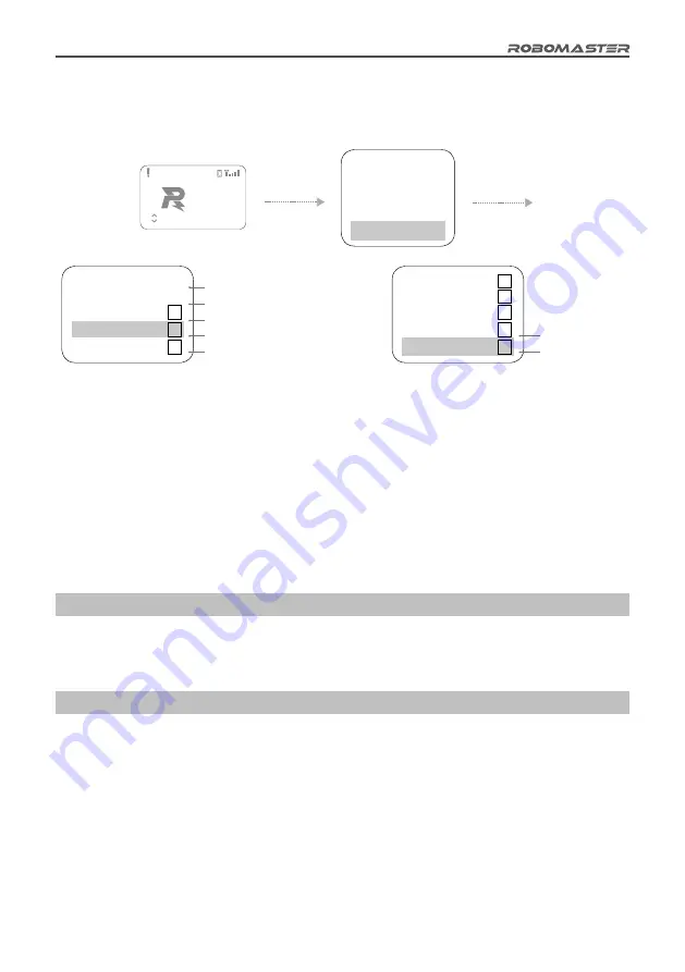
Debug Function
Through the interaction interface, access the "Debug Option" menu, where you can modify the advanced
settings of the Referee System, as shown in detail below:
11 MODULES
FAULT
LightInd Offline
Press and
hold the
OK key
Press the
OK key
Robot Type
Module
Game
Wi-Fi
Debug
Setup
Setup
Setup
Setup
Option
Module State Info
Ext Module Setup
Ext Speed Mon
Module Detection
Offline Mode
√
√
Defective Module Error Information
Extra Module Function Settings
Extra Speed Monitor Module Settings
Offline Module Detection Settings
Offline Mode Settings
Ext Module Setup
Module Detection
Offline Mode
All Lights Control
Bullet Test
√
√
All Lights Control
17mm fluorescent
projectile
brightness test
"Ext Speed Mon" indicates that the robot is equipped with an extra 17mm-projectile Speed Monitor
Module. This setting is saved when powered off.
"Module Detection" can test whether the module is offline. If the module is offline, the Light Indicator
Module will display the offline light and the UI will display the offline information. This setting is not saved
when powered off.
In "Offline Mode", the Robot Side is offline. One of its features enables the "Chassis", "Gimbal", and
"Ammo-Booster" power output ports of the Power Management Module to have normal power supply.
This setting is saved when powered off.
"All Lights Control": The robot indicator lights show that this function is enabled. This setting is not saved
when powered off.
"Bullet Test": The 17mm-projectile Speed Monitor Module is used for a fluorescent projectile brightness
test. This setting is not saved when powered off.
Introduction to the Robot Side Module Initialization
To ensure fair competition, it is important that all of the Referee System modules are working properly.
Therefore, the Robot Side will initialize each module after power up. When the initialization of an
important module fails, a solid yellow light will appear on the Light Indicator Module.
Video Transmitter Module (VT02 & VT12) Instructions
The Video Transmitter Module has a transmitter and a receiver.
When the Video Transmitter Module is used for the first time, the VTM Transmitter and VTM Receiver
must be respectively activated in your region by using RoboMaster Tool 2. For the download website,
refer to the "RoboMaster Tool 2 Upgrade Procedure" section.
Activation of the VTM Transmitter
1. Install the USB driver of the Main Controller Module by referring to the "RoboMaster Tool 2 Upgrade
Procedure" section.
2. Connect the VTM Transmitter and the Main Controller Module to the Power Management Module of
the Referee System, and use a micro-USB data cable to connect your PC to the USB port of the Main
Controller Module to supply power to the Power Management Module.


