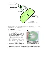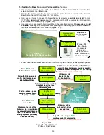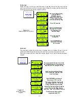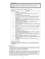
Figure 1.11 –
External Base Station Setup
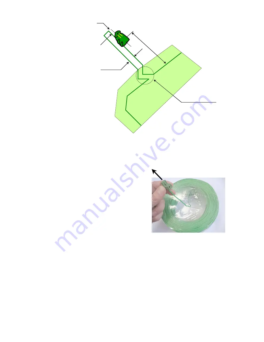
26cm /10“
Triangle as done in
narrow pass type B
(refer to Figure 1.7)
Re
com
m
en
de
d
(up
to
3m
/1
0ft)
Base Station is placed with a right
shift of 10-20cm (4-8“)
(not aligned with the wire)
Recommended to continue
the wire for at least 25cm
(10”) after the Base Station
26cm /10“
Triangle as done in
narrow pass type B
(refer to Figure 1.7)
Re
com
m
en
de
d
(up
to
3m
/1
0ft)
Base Station is placed with a right
shift of 10-20cm (4-8“)
(not aligned with the wire)
Recommended to continue
the wire for at least 25cm
(10”) after the Base Station
1.4 Perimeter Wire Setup
Now, knowing the location of the Base Station and the planning of the wire layout, you can begin to
setup the Perimeter Wire in the Base zone.
1.4.1 Starting
Point
Place the Base Station according to your plan
with the fence towards the inner side of the
lawn, as shown in Figure 1.11 or 1.13;
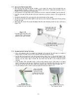
Puncture the plastic covering of the perimeter
wire and pull the wire ends with the plot
connector out of the plastic covering; The
connector should be connected to the wire in
the polarity show in Figure 1.12;
The plastic covering is designed as a dispenser
for the wire; so do not remove the wire spool
from the covering;
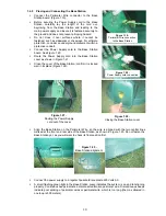
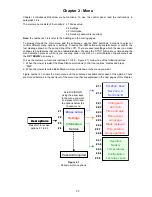
Peg the beginning of the wire to the ground
where the Base Station will be located; be sure
to leave 30cm (12 inches) to close the loop at
the end of the setup (Figure 1.13);
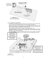
Figure 1.12 –
Pull out the wire from the
plastic covering – do not remove the
covering; it is designed as a dispenser.
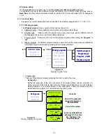
Start laying the wire to the counterclockwise
direction when standing inside the lawn, as
show in Figure 1.13.
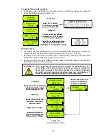
Begin pulling the perimeter wire out of the plastic covering and lay it loosely as you walk along the
area of the lawn to the direction shown in Figure 1.13;
17


