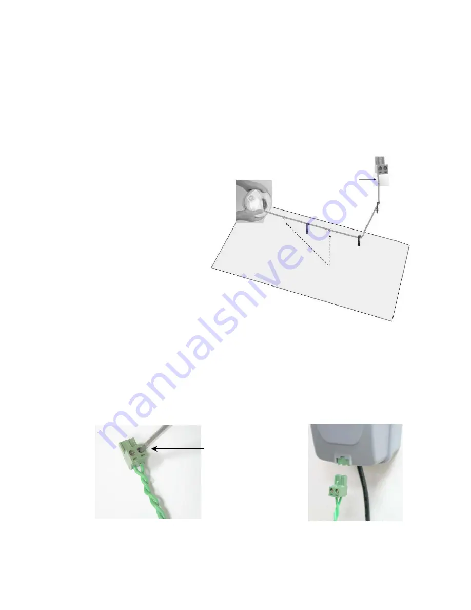
1.7.3 Laying Out The Perimeter Wire
Now, knowing the Perimeter Switch location, you can begin the setup of the Perimeter Wire, as
was explained in articles 1.2 and 1.3. The perimeter wire setup in a Base and non-Base zone is
identical in terms of placement and fastening;
At the location of the perimeter switch, strip back
5 mm (0.2 inches) of insulation from the wire end.
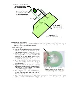
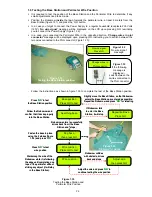
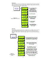
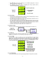
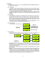
Insert the wire end to the left side of the plot connector, as shown in figure 1.39 and tighten the
screw.
Peg/fix the beginning of the wire where the Perimeter Switch will be located;
Lay the wire from the Perimeter Switch to the lawn; be sure to leave enough wire at the beginning
to close the loop;
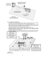
Start laying the wire to the counterclockwise direction when standing inside the lawn, as show in
Figure 1.39.
26
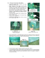
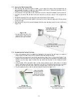
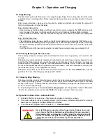
Figure 1.40
Inserting and Fastening
Perimeter Wire to Connector
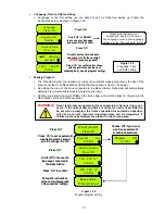
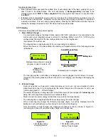
Figure 1.41
Plug the plot connector into
the Perimeter Switch
Using a small flat
blade screwdriver,
tighten the screw
to secure the perimeter
wire into the connector
1.7.4 Completing And Testing The Setup
Connect the wire end to
the left side of the plot
connector (when looking
towards the screws)
Perimeter wire layout
in
counter
clockwise direction (as view from
the inner side of the lawn)
Figure 1.39
Connecting the wire end to the
left side of the connector and
perimeter wire layout direction
Once the perimeter wire is completed and pegged to the ground, the last step to complete is
attaching the Perimeter Switch to the perimeter wires and testing the setup.
Pull the two loose perimeter wire leads taut and peg them down to the ground (figure 1.36),
adjacent to one another, as you move away from the perimeter and towards the Perimeter Switch
location (use the same pegs to attach the two wires from the lawn to the Perimeter Switch
location).
At the location of the perimeter switch, cut the loose perimeter wire so both wires are of equal
length, removing any excess wire. Strip back
5 mm (0.2 in) of insulation from the wire end. Insert
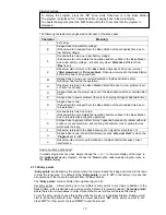
the wire end to the free hole in the connector and tighten the screws as shown in figure 1.40.
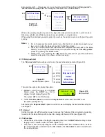
Plug the perimeter wire connector into the Perimeter Switch (see figure 1.41)


