16
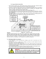
Add pegs in to pull
the perimeter wire down
to the ground surface,
below the grass tips.
Add pegs in to pull
the perimeter wire down
to the ground surface,
below the grass tips.
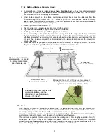
Pegs should be driven at distances between one another
that will keep the wire down below the grass level and
prevent it from becoming a tripping hazard (Figure 1.13).
When properly fastened to the ground, the wire and pegs
will soon disappear under the growth of new grass and will
not be visible.
If additional wire is required in order to complete the set-
up, use the wire connectors provided, which are
waterproof, to connect between the two wire ends, as
explained in chapter 5.5.
1.3.4 Completing The Perimeter Wire Setup
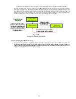
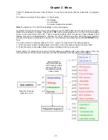
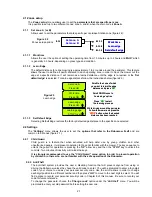
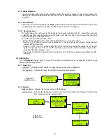
Once the perimeter wire is completed and pegged to the ground, the last step to complete is attaching
the Perimeter Switch to the perimeter wires and testing the setup.
Pull the two loose perimeter wire leads taut and peg them down to the ground (figure 1.2), adjacent to
one another, as you move away from the perimeter and towards the Perimeter Switch location (use the
same pegs to attach the two wires from the lawn to the Perimeter Switch location).
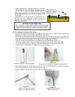
There are two loose wire ends where the perimeter wire set up was started (Figure 1.14).
Use the same peg to fasten these two perimeter wire ends down to the ground and twist them.
Cut the wire end without the connector so they are of equal length - removing any excess wire.
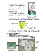
Strip back 6 mm (0.25 inches) of insulation from the wire end (Figure 1.15).
Insert the free perimeter wire into hole of connector using a small flat screwdriver; tighten the screw to
secure the perimeter wire into the connector (Figure 1.16).
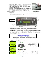
Plug the perimeter wire connector into the Perimeter Switch (see figure 1.17)
IMPORTANT INFORMATION!
Screw terminals or twisted cables, insulated with insulation tape
is not a satisfactory splice. Soil moisture will cause the stripped
wire ends to oxidize and after a while result in broken circuit.
Figure 1.13 -
Pegging the Perimeter Wire
Figure 1.17
Plug the plot connector into
the Perimeter Switch
Figure 1.15 -
Strip 6mm (0.25 inches) of insulation from the wire end
Figure 1.14 -
Two loose wire ends at the starting point
Figure 1.16 -
Tighten the screw to secure the
perimeter wire into the connector

