background image

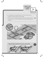
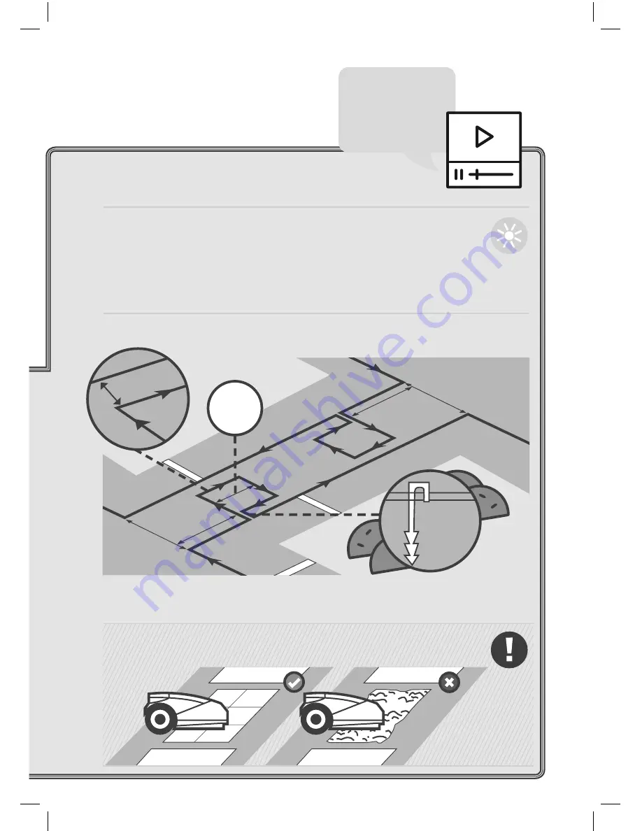
14 cm [5.5 in] 

32 cm

[12.6 in]

Main Zone

Sub Zone

Two wires 

under 

same peg

70 cm

 [27.

5 in

Min 5

0 cm (

19.7

 in)

Min 5

0 cm (

19.7

 in)

70 cm

 [27.

5 in

28

29

•  If a Narrow Pass is shorter than 2 m [7 ft], set up only one 

square Perimeter Island in the passage 

•  Take care to wire Narrow Passes correctly to ensure that the 

mower doesn’t cross into different zones spontaneously while 

mowing

Narrow Passes should be firm, level, and smooth.

TIPS

A helpful video 

is available 

online

Summary of Contents for RS615 Pro

Page 1: ...Robotic Mower RS635 Pro S RS625 Pro RS615 Pro RS615u EN User Guide See how to install Original Operating Instructions ...

Page 2: ...n I m Robomow nice to meet you Your safety is important to us Please review this Manual carefully for all safety warnings and take extra caution to keep both children and pets off the lawn when Robomow is in operation ...

Page 3: ...1 Safetyfirst 2 Installation 13 Quick reference 46 ...

Page 4: ...ORTANT READ CAREFULLY BEFORE USE KEEP FOR FUTURE REFERENCE Warning decal definitions Safety warnings precautions Safety features Do not allow children to use or operate the mower Children must be supervised at all times ...

Page 5: ...ollow all safety instructions and warnings 2 Read the Safety Manual carefully before operating your mower 3 Be careful of thrown objects during operation 4 Keep a safe distance from the mower while it is operating Keep people especially children pets and bystanders away from the area where the mower is operating 5 CAUTION Do not touch rotating blade Keep hands and feet away and do not lift the mow...

Page 6: ...s about the risks and that it is forbidden to enter your lawn while the mower is operating 5 If your lawn is open to the street and or your neighbors you must be present during the mower s operation to prevent others from accessing your lawn Alternatively you must protect fence your lawn so that others do not access the mower during operation B Preparations 1 Ensure the correct installation of the...

Page 7: ...ely stopped rotating 6 Donotusethemowerforanypurposeotherthancuttinglawn 7 Keep all guards shields safety devices and sensors in place Repair or replace damaged parts including decals 8 Set the weekly program at times when there are no people on the grass 9 Do not connect a damaged power cord to the supply or touch a damaged cord before it is disconnected from the supply as it can lead to contact ...

Page 8: ...f the Safety Switch D Transportation Within the working area 1 Press the STOP button to stop the mower 2 Use the Remote Control available as an accessory or via the mobile App to drive it from one place to another 3 In case of different ground height level switch off the Safety Switch and carry the mower by its carrying handle lift the STOP button for that ...

Page 9: ...nually in slopes greater than 15 degrees or where a firm footing is not possible F Batteries 1 Do not open or damage the battery pack 2 The Battery Pack contains electrolytes In case of an electrolyte leakage from the Battery Pack the following actions should be taken Skin contact Wash the contact areas off immediately with water and soap Eye contact Immediately flush the eyes with plenty of clean...

Page 10: ... 4 Do not perform maintenance barefoot or wearing open sandals Always wear suitable work shoes and long trousers 5 Replace worn or damaged parts for your safety 6 Use only original equipment and accessories It is not permitted to modify the original design of the mower All modifications are made at your own risk 7 Ensure that only replacement cutting means of the right type Part No MRK6101A are us...

Page 11: ...onment 2 Do not dispose of the mower or any other of its parts including the Power Supply and Base Station as unsorted municipal waste they should be collected separately 3 Ask your local distributor dealer about return and collection systems availability 4 Do not dispose of the battery pack in a fire and do not place used batteries in your household trash 5 The battery must be collected recycled ...

Page 12: ...dental press of one of the buttons Only pressing two buttons in the right order will initiate the operation It is required to activate the Child Lock feature if children under age 6 may come in contact with the mower B Anti Theft Disabling Device The Anti Theft Disabling Device system function will prevent anyone from using or driving the mower unless they have a valid code to enter You will be pr...

Page 13: ...ovement in that direction and reverse itself away from the obstacle F Emergency Stop Button Pressing the STOP button at any time during operation will stop the mower and the blade immediately G Safety Switch Switching off the Safety Switch will prevent any operation of the mower It is required to switch it off before lifting the mower and before any maintenance is done H Base Station Perimeter Swi...

Page 14: ...12 Let s get started Can t wait to mow your lawn ...

Page 15: ...from its base on predetermined days and times mow your lawn and return to base for charging A preinstalled perimeter wire sets the boundaries a virtual wall for your mower It will be laid around the edges of your lawn and objects that you want to protect The mower moves randomly within its working area as defined by the perimeter wire This kind of random movement provides the perfect cut and ensur...

Page 16: ...our lawn to give it a perfect finish Good looking lawns are achieved by consistent mowing which is exactly what a robotic mower provides After following the clear installation instructions you will be ready to enjoy your free time while your new friend looks after your lawn ...

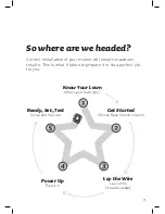
Page 17: ...ll ensure maximum results This is what it takes to prepare it to do a perfect job for you Know Your Lawn What s your lawn type Get Started Choose Base Station location Power Up Plug it in Ready Set Test Setup and trial run Lay the Wire Lay out the virtual boundary ...

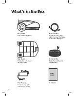
Page 18: ...ation This is where the mower recharges itself Extension Cable 20 m 65 ft low voltage cable to connect the mower to the Power Supply unit Perimeter Wire Marks the working area for the mower Power Supply The power supply for charging your mower User Guide USER GUIDE ...

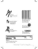
Page 19: ...the Base Station RoboRuler For measuring the Perimeter Wire s distance from the lawn s edge Base Station Stakes x6 For affixing the Base Station to the ground Fuse For preventing battery discharge during storage Wire Pegs For securing the wire to the ground Wire Connectors For splicing the Perimeter Wire in case of a cut ...

Page 20: ...will save you unnecessary mistakes and make the installation process easier and more straight forward Know Your Lawn Type B Main Zone Sub Zone Your lawn consists of more than one zone These zones are connected by a narrow passage 1 5 4 m 4 5 14 ft wide The mower can drive between these zones to mow the entire area You can also skip some later sections in this manual that are not relevant to your l...

Page 21: ...arrow pass up to 4 m 14 ft wide and some areas are totally separated from the Main Zone by a fence sidewalk pathway or other obstacle and the mower can t drive between them Type C Main Zone Separated Zone Your lawn consists of two or more zones that are not connected separated by a fence sidewalk pathway or other obstacle The mower cannot drive between these zones ...

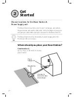
Page 22: ...cation for the Base Station Choose locations for the Base Station Power Supply unit Get Started Consideration A Up to a max of 20 m 65 ft from a power outlet Where should you place your Base Station The Base Station will be installed at a later stage after the Perimeter Wire is in place TIP Power Supply unit Base Station 20 m 65 ft Extension cable low voltage ...

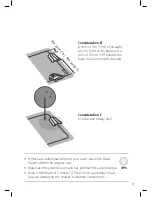
Page 23: ...t there are no slopes Keep a minimum of 1 meter 3 3 feet from a sprinkler head to avoid damaging the mower s internal components Consideration B A min of 3 m 10 ft of straight wire in front of the base and a min of 30 cm 1 ft behind the base to allow smooth docking Consideration C In a flat and shady spot M i n 3 m 1 0 f t M i n 3 0 c m 1 f t ...

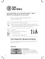
Page 24: ...nation pliers Lay the perimeter wire virtual boundary which defines the working area for the mower Lay the Wire TIPS Soft Obstacles Soft obstacles are flower beds ponds or small trees They need to be protected by creating Perimeter Islands OBSTACLES Now you re ready to install the Perimeter Wire Let s take it step by step A sunny day and a sunny mood First Things First Obstacles and Slopes Before ...

Page 25: ...er Island If the diameter is larger it s not necessary Slopes along the edge To ensure your mower doesn t slip off the lawn especially when the grass is wet the Perimeter Wire must exclude a slope along the edge of your lawn with an incline of over 15 that is 15 cm rise per 1 m 6 in rise per 3 ft TIP Slopes within the Lawn Your mower can mow areas within the lawn with a slope of up to 35 35 cm ris...

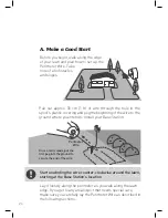
Page 26: ...starting at the Base Station s location Peg Once a tail is made put the first peg into the ground to secure the end of the wire Perimeter Wire A Make a Good Start Before you begin walk along the edge of your lawn and plan how to set up the Perimeter Wire Take note of all obstacles and slopes Pull out approx 30 cm 1 ft of wire through the hole in the spool s plastic covering and peg the beginning o...

Page 27: ...nimum of 1 2 m 4 ft if the edge of the lawn borders water When the edge is flat or a drop use the short distance of the RoboRuler When the edge is a wall more than 2 cm 1 above the ground level use the longer distance of the RoboRuler 40 cm 1 3ft B Maintain Proper Distance The Perimeter Wire is secured to the ground by the pegs supplied with the product Use the RoboRuler to determine the distances...

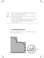
Page 28: ...s such as pavements is usually recommended If additional Perimeter Wire is required in order to complete the setup you can extend it using the waterproof Wire Connectors provided see section 5 G Splicing the Perimeter Wire TIPS C Make Smooth Turns Maintain a 45 angle at all left turn corners when laying the wire along the perimeter 20cm 8 in ...

Page 29: ...eter Island or won t be able to mow the area around it properly TIPS D Protect Soft Obstacles Objects such as flower beds ponds or small trees must be protected by setting Perimeter Islands Keep min 1 5 m 5 ft between islands if obstacles are closer together use one island If the distance between an island and the perimeter wire is lower than 1 5 m 5 ft make the obstacle part of lawn s edge Perime...

Page 30: ...rated Zone Main Zone Main Zone Sub Zone Main Zone Sub Zone Separ Zone Recall Your Lawn Type Sub Zone Main Zone Narrow Pass Main Zone A Narrow Pass connects the Main Zone with a Sub Zone To allow your mower to drive through it should be at least 1 m 3 5 ft wide Don t have a Sub Zone Skip this section E How to Wire a Sub Zone Type B Type D ...

Page 31: ...cm 27 5 in 29 If a Narrow Pass is shorter than 2 m 7 ft set up only one square Perimeter Island in the passage Take care to wire Narrow Passes correctly to ensure that the mower doesn t cross into different zones spontaneously while mowing Narrow Passes should be firm level and smooth TIPS A helpful video is available online ...
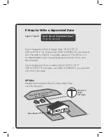
Page 32: ...p this section Type C Type D If your Separated Zone is larger than 120 m2 1291 ft2 200 m2 2150 ft2 for models over 3000 m2 30000 ft2 your mower won t be able to finish it in a single operation Therefore it is recommended to wire it separately and connect it to its own Base Station If your Separated Zone is smaller than 120 m2 1291 ft2 200 m2 2150 ft2 for models over 3000 m2 30000 ft2 you can wire ...

Page 33: ...31 OPTION 2 Wire the Zone separately and connect it to a Perimeter Switch optional accessory Perimeter Switch Separated Zone smaller than 200 m2 2150 ft2 Main Zone Power Supply unit and Base Station ...

Page 34: ...s of the wire that meet at the Base Station should be joined together G Complete Wire Setup Use the same peg to fasten both tail ends of the wire to the ground Trim the ends so both wires are the same length TIPS Make sure you twist the two wires together properly ...

Page 35: ...33 Strip back 5 mm 0 2 in of insulation from the wire ends insert the twisted wire into the connector and secure it using a small flat screwdriver Yay You ve done the hardest part ...

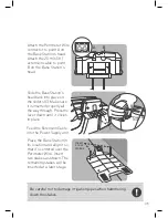
Page 36: ...on A Install and Connect the Base Station Power Up B Push A Pull A B Place the Base Station in its planned location Remove the Base Station s head from the Base A Pull the lever upward B Push the Base Station s head from the front side in the direction marked Install and connect the Base Station and Power Supply ...

Page 37: ...e Perimeter Wire connector to point A on the Base Station s head Attach the 20 m 65 ft extension cable to point B on the Base Station s head Place the Base Station in its location and align it so that it s centered over the Perimeter Wire Insert two stakes as shown The remaining stakes will be inserted at a later stage Insert 2 rear stakes B A Be careful not to damage irrigation pipes when hammeri...

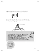
Page 38: ...ocation near a power outlet Position it outside the lawn perimeter A dry and sheltered location is preferable TIP Power Supply unit Base Station 20 m 65 ft Extension cable low voltage Make sure the connector is inserted the whole way up to the white mark Connect the DC cable from the Power Supply unit to the 20 m 65 ft extension cable 36 ...

Page 39: ...reen if the mower is inside the Base Station The Extension Cable from the Power Supply to the Base Station should be securely fastened to the ground It should never present a tripping hazard The Extension Cable should cross ONLY over soft surfaces It should not cross over hard surfaces e g sidewalk driveway where it cannot be securely fastened Caution Just one more step to go 37 ...

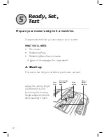
Page 40: ...champagne or equivalent A Start up There are a few things to do before your mower can start Ready Set Test Adjust the cutting height 20 80 mm 0 8 3 in by turning the mowing height adjustment knob while pushing it down Prepare your mower and give it a test drive Cover Door Mowing Height Adjustment Knob Mowing Height Indicator Safety Switch ...

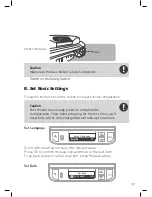
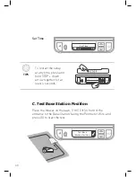
Page 41: ...do a first time charge that will take up to 24 hours B Set Basic Settings Follow the instructions on the screen for a quick initial configuration Set Language Select language English Scroll with the arrows to select the desired value Press GO to confirm the selection and move to the next item To go back a step or cancel an action press the back arrow Set Date Set Date OK 17 09 2016 Insert the fuse...

Page 42: ...ce the mower on the lawn 3 m 10 ft in front of the entrance to the Base Station facing the Perimeter Wire and press GO to start the test TIPS To restart the setup at any time press and hold STOP down arrow together for at least 4 seconds Set Time Set Time OK 13 45 ...

Page 43: ...wer Supply unit extension cable and Base Station wires are all connected properly Check for possible Perimeter Wire cuts If the Change wires in plot connector message is displayed swap the wires at the plot connector If the Reposition Base Station message is displayed check that the Base Station is aligned with the Perimeter Wire Move any obstacles preventing entry into the Base Station Be careful...

Page 44: ...ill drive back to the Base Station D Test Perimeter Wire Walk alongside as the mower tours the perimeter At the end of a successful tour the message Wire test succeeded will be displayed and the mower will reenter the Base Station Press GO If the Adjust wire message is displayed and the mower stops and drives backwards move the wire slightly inward and press GO to continue the wire test Test Wire ...

Page 45: ...are nearby Make sure the lawn is clear of debris G Charge your mower Place your mower on the Base Station and let it fully charge before its first mow up to 24 hours Once it is fully charged it will depart automatically according to its mowing schedule F Finish Installing the Perimeter Wire Insert the remaining pegs along the Perimeter Wire approx 1 m 3 3 ft apart Hammer the extension cable into t...

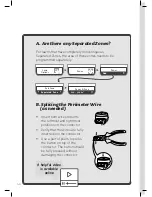
Page 46: ...eeded Zones Add Sub Zone Separated Zone Zones A Area 200 300 m2 Lawn Options Zones Insert both wire ends into the leftmost and rightmost positions on the connector Verify that the wires are fully inserted into the connector Use a pair of pliers to press the button on top of the connector The button should be fully pressed without damaging the connector A helpful video is available online ...
Page 47: ...45 Well Done Now relax and let your mower do the work ...

Page 48: ...46 Knowing your mower Menu structure Automatic operation Manual operation Features how to Periodic maintenance Troubleshooting FAQs ...

Page 49: ...naboutitsdifferentparts and messages Understanding how it works and interacts will lead to its smooth and easy operation Knowing your mower External Parts Operating Panel Operating Light STOP Button Carrying Handle Touch Sensitive Bumper ...

Page 50: ...48 Under the Hood Parts Cover Door Mowing Height Adjustment Knob Safety Switch Fuse Storage Mowing Height Indicator Operation Panel ...

Page 51: ... is used to cancel a selection or go one step back in the menu Battery is charging balancing battery cells Anti theft is activated Current Day and Time Battery is fully charged Ready Next operation time Displayed when a mowing cycle is completed and the battery is fully charge Mo 06 00 Mowing Schedule is On Mowing Schedule is Off Mower is in winter charging Su 11 28 ...

Page 52: ...er wire signal is OK the mower is inside the base Blinking green Perimeter wire signal is OK the mower is outside the base Blinking red fast Perimeter wire is damaged or disconnected Blinking red slow Poor perimeter wire connection or the wire is too long Steady red Faulty power supply ...

Page 53: ...awn and mowing parameters Inactive Time Set mowing free times Mowing Extent Set how often to mow your lawn Islands Switch Islands feature on off Near Wire Follow Reduce wheel tracks along lawn s edge Smart Mow Increase mowing efficiency Turbo Mow Enable faster and stronger cut use for first cut of the season Zones Add remove or edit zones Program On Off Enable Disable automatic operation by zone ...

Page 54: ... Rain Sensor Automatically halt operation in rain humid weather Anti Theft PIN Code protection and alarm in case of theft Language Change mower s menu language LCD Contrast Adjust the LCD s contrast Child Lock Lock the keypad to prevent accidental press RoboHome RoboHome accessory on off RoboHome ...

Page 55: ...e Base Station until the next cycle begins The interval between mowing cycles is defined by the Mowing Frequency setting If required extra mowing time can be added via the Mowing Hours setting to improve mowing results Learn how to configure automatic operation and manually bypass override it when needed Automatic operation Tell your mower how often to mow Mowing Frequency controls the periodicity...

Page 56: ...g Hours percentage The default is 0 Lawn Options Scroll to select Mowing Extent from the Lawn Option Menu Press Go Mowing Hours Mowing Frequency All Zones By Zone Set Mowing Hours 10 Scroll to select Mowing Frequency Press Go to select Days Scroll to select All Zones By Zone If By Zone is selected scroll to select zone Press Go Scroll to change mowing frequency The default frequency is Medium Scro...

Page 57: ...lot and press Go You can configure up to 2 time slots Scroll to toggle the inactive window On Off Press Go Set the start and end times for this time slot Scroll to select OK Press Go Lawn Options Scroll and press Go to select On Off Lawn Options The Program On Off menu allows pausing automatic operation in a particular zone of your lawn When Program is set to Off in a particular zone the mower wil...

Page 58: ...ll to the zone you want the mower to mow Press Go Press Go Scroll to the operation mode Edge Mow or Mow Only Press Go PUSH A B Features how to Adjusting the mowing height Lift the Bumper Door at the top of the mower Set the mowing height by turning knob A while pushing it down The cutting height is displayed to the left of knob B The mowing height s range is 20 80 mm 0 8 3 in Zone Main Zone A ...

Page 59: ... this feature is turned Off To turn it On for the first time Scroll using the arrows to select Anti Theft from the Mower Option Menu Scroll to set the PIN Code Press Go after each digit to move to the next one Press Go to OK Reenter the same 4 digit PIN Code to confirm Press Go to OK Scroll to select On Press Go Anti Theft On Anti Theft 0 0 0 0 OK Anti Theft 1 0 0 0 OK Mower Options Child Lock Thi...

Page 60: ...the ground In case of seasonal changes in the lawn make sure to adjust the wire accordingly Inspect the Base Station clean it from mud and debris to allow proper docking WARNING Severe injury and damage hazard Always turn the Safety Switch off before lifting the mower Blades are very sharp They can cause severe cuts or lacerations Always wear heavy work gloves when working with or around the blade...

Page 61: ... the Safety Switch and inspect the blades Remove any foreign object or excessive clogging inside the mowing deck Raise the mowing height and switch the TurboMode on Check Power There is a temporary power cut Confirm that the Power Supply unit is plugged in into mains The Power Supply unit is not plugged in properly Confirm the Power Supply is plugged in There is no charging source detected Clean t...

Page 62: ...g The blades may be dull Switch off the Safety Switch and try swapping between blades or replacing them Use heavy gloves when inspecting blades The grass may be wet For the best cut operate the mower when the grass is dry It is recommended not to mow in the early morning hours Patchy and uneven mowing Minimize Inactive Time to allow the mower to complete Mowing Cycle quicker If it is the fast grow...

Page 63: ...1 Learn Your Lawn Contact us DOC6011G_EN ...

Reviews: