background image


9


GENERAL INFORMATION 


ENG


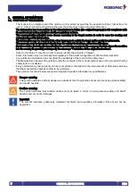
1.3.2.  PICTOGRAMS INDICATING PROHIBITION  


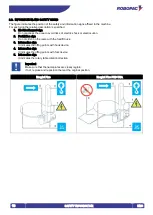
The following table summarises the safety-related pictograms indicating PROHIBITION. 


GENERIC PROHIBITION 


NO SMOKING 

Smoking is not allowed in the area where this sign is located. 


NO NAKED FLAMES 

This symbol prohibits the use of naked flames near the machine or parts of it to prevent a fire hazard. 


NO PEDESTRIANS 

Pedestrians are not allowed to pass through the area where this signal is located. 


DO NOT EXTINGUISH WITH WATER 

Any fire that may occur near the machine or parts of it must NOT be extinguished with jets of water. 


DO NOT INSERT YOUR HANDS 


DO NOT PUSH 


DO NOT SEAT DOWN 


DO NOT CLIMB ONTO THE SURFACE 


DO NOT REMOVE THE OPERATOR GUARDS 


Summary of Contents for ECOPLAT PLUS BASE

Page 1: ...INTENANCE MANUAL N matricola Serial number Serienummer N d identification Matricula n Cod 3709304595 Ed 19 02 ROBOPAC S p a Via Fabrizio da Montebello 81 47892 Repubblica di San Marino Phone 378 0549 910511 Fax 378 0549 908549 Translation of original instructions ENG ...

Page 2: ...ENG 2 Page left blank intentionally ...

Page 3: ... 3 1 MACHINE GENERAL DESCRIPTION 21 3 1 1 MACHINE MODELS DESCRIPTION 23 3 2 DESCRIPTION OF THE OPERATION CYCLE 24 3 3 SAFETY DEVICE DESCRIPTION 25 3 4 DESCRIPTION OF ELECTRICAL DEVICES 26 3 4 1 REMOTE CONTROL SOFTWARE 27 3 5 DESCRIPTION OF ACCESSORIES ON REQUEST 28 3 6 TECHNICAL SPECIFICATIONS 29 3 6 1 MACHINE DIMENSIONS 29 3 6 2 MACHINE TECHNICAL FEATURES 30 3 6 3 INSTALLED POWER 30 3 6 4 SPOOL F...

Page 4: ...DELAY 58 6 7 CYCLE START AND STOP 59 6 8 EMERGENCY STOP AND RESTART 60 6 9 SPOOL LOADING 61 7 MAINTENANCE INFORMATION 62 7 1 RECOMMENDATIONS FOR MAINTENANCE 62 7 2 PERIODICAL MAINTENANCE INTERVALS 63 7 3 LUBRICATION POINT DIAGRAM 64 7 4 LUBRICANT TABLE 65 7 5 MACHINE CLEANING 66 8 FAULT INFORMATION 67 8 1 ALARM MESSAGES 67 9 REPLACEMENT INFORMATION 69 9 1 RECOMMENDATIONS FOR REPLACING MACHINE PART...

Page 5: ... the message Translation of the original instructions Refer to the table of contents in order to easily identify the subjects of interest Some information may not correspond completely to the actual configuration of the machine delivered Any additional information does not affect the readability of the text and the safety level The Manufacturer reserves the right to modify the contents of the manu...

Page 6: ...ontains references and indispensable operating safety indications 1 Machine model 2 Machine serial number 3 Year of manufacture 4 Power supply voltage 5 Power supply frequency 6 Power supply phases 7 Absorbed electric current 8 Installed power 9 Air consumption 10 Air supply max pressure 11 Machine weight 12 Manufacturer s identification 13 Name ...

Page 7: ...e Therefore the technician must have accurate information and competences with particular skills in the field of intervention Format changeover Set of operations to carry out on the machine before starting to work with characteristics other than the previous ones Training Training process aimed at transferring to the new operator the knowledge skills and behaviours required to operate the machine ...

Page 8: ...a risk of electric shock ATTENTION DANGER DUE TO FLAMMABLE MATERIAL ATTENTION DANGER DUE TO MOVING PARTS ATTENTION DANGER DUE TO HIGH TEMPERATURES ATTENTION DANGER DUE TO SUSPENDED LOADS ATTENTION DANGER DUE TO CONTACT WITH OVERHEAD OBSTACLES ATTENTION TRIPPING OR FALLING DANGER ATTENTION TANGLING DANGER It signals to the concerned personnel that the device bearing this pictogram features parts wh...

Page 9: ...FLAMES This symbol prohibits the use of naked flames near the machine or parts of it to prevent a fire hazard NO PEDESTRIANS Pedestrians are not allowed to pass through the area where this signal is located DO NOT EXTINGUISH WITH WATER Any fire that may occur near the machine or parts of it must NOT be extinguished with jets of water DO NOT INSERT YOUR HANDS DO NOT PUSH DO NOT SEAT DOWN DO NOT CLI...

Page 10: ...ATION TO WEAR PROTECTIVE GOGGLES The presence of the symbol next to the description requires the use of safety goggles by the operator since the risk of injury is implicit OBLIGATION TO WEAR A PROTECTIVE HELMET The presence of the symbol next to the description requires the use of a protective helmet by the operator since the risk of injury is implicit OBLIGATION TO WEAR A PROTECTIVE MASK The pres...

Page 11: ...lled commercial devices if necessary for machine use Unpacking and installation instructions Quick guide for quick start USB pendrive containing the information listed below Use and maintenance manual translated into various languages Spare parts catalogue Machine programming software Wiring Diagrams 1 6 HOW TO READ THE INSTRUCTIONS FOR USE The manual is divided into chapters each of which describ...

Page 12: ...ents can be caused by a careless use of the machine by the operator Usually it is too late to remember what should have been done when the accident has already happened Caution warning Preserve the readability of the information signs and observe the indications given The information signs may have different shapes and colours indicating hazards obligations prohibitions and indications Tampering w...

Page 13: ... personnel involved Provide proper safety conditions when operating in high areas that are dangerous or hard to access Install the machine according to the minimum perimeter spaces indicated by the Manufacturer and the surrounding working activities Prepare a machine installation project if the machine is to interact directly or indirectly with another machine or with a production line The project...

Page 14: ...ective Equipment indicated in the Instructions for use in particular safety shoes and that provided for by the laws in force on matter of safety in the workplace Always keep the perimeter areas in suitable conditions and free from obstacles in order to minimise the risks for the operator especially near the control station The machine must be used by one operator only that must be appointed and au...

Page 15: ...ntended by the Manufacturer Do not use or let the machine be used with defective deactivated and or incorrectly installed safety devices Do not continue to use the machine if malfunctions have been detected Stop the machine immediately and restart it only after the normal conditions of use have been restored Never carry out an intervention with the machine in operation but only after stopping it p...

Page 16: ... operators The residual risks are all the risks that persists although all safety solutions have been applied and integrated during machine design The list specifies the residual risks specific for this type of machine Risk of slipping Do not climb on machine parts during its operation Risk of impact Do not approach machine parts during its operation Risk of shearing upper limbs Do not insert your...

Page 17: ...table with the lifting device during machine operation Risk of falling or ejected objects Do not use the machine at a speed which is not suitable for the type of product to be wrapped If the packages to be wrapped contain unstable and dangerous elements it is necessary to implement appropriate safety measures e g perimeter protections to avoid risks of injuries to persons ...

Page 18: ...ccordance with the applicable laws All the extraordinary maintenance interventions shall be carried out only by authorised personnel with experience and expertise in the field of intervention Important Non compliance with the instructions given may cause risks to the safety and health of people as well as economic damages 2 7 SAFETY WARNING FOR THE ELECTRICAL EQUIPMENT The electrical equipment has...

Page 19: ...sks of electric shock or electrocution 2 Prohibition sign Do not climb on the ramp with the forklift truck 3 Information sign It indicates the lifting points with hook device 4 Information sign It indicates the lifting points with fork device 5 Information sign It indicates the rotary table rotation direction Important Make sure that the nameplates are clearly legible If not replace and reposition...

Page 20: ...ENG SAFETY INFORMATION 20 2 9 PERIMETER AREAS The illustration shows the perimeter working areas of the machine 1 Operator standing area 2 Pallet loading unloading area 3 Perimeter area ...

Page 21: ...hine consists of a rotary table which makes the pallet turn and a spool carriage which unwinds and stretches the film The machine is equipped with a series of safety devices designed to avoid any injuries to the operator or other persons using the machine It comes in different models to satisfy different market needs Stretch film spools commonly available on the market are used for load wrapping T...

Page 22: ...information purposes only the machine models and the legend lists the parts Legend 1 Slide shaft 2 Table motor 3 Rotary table 4 Carriage motor 5 Control panel 6 Film carriage 7 Base 8 Loading unloading ramp 9 Autotransformer Ecoplat Plus Ecoplat Plus FRD USA ...

Page 23: ...f machine General features Ecoplat Plus Ecoplat Plus FRD Ecoplat Plus FRD USA Ecoplat Plus with film carriage type FRD or FRD for net Table Film carriage features Film carriage type General features FRD Film carriage type FRD and FRD for net with roller with clutch mechanical brake and manual film stretching adjustment ...

Page 24: ...sk of crushing upper limbs Do not insert the film in the gripper by hand Phase 2 Once the cycle has started the rotary table starts to turn while the film carriage unwinds the film for the entire height according to pre set parameters Phase 3 Once the wrapping phase has ended the machine stops for manual film cutting Phase 4 The operator unloads the pallet The cycle is complete and the machine is ...

Page 25: ...tacles under the carriage 2 Film carriage mechanical locking device it immediately stops the fall of the film carriage in case of accidental breakage of the lifting chain 3 Main switch it enables and disables the power supply It can be locked to prevent unauthorised persons from enabling it during machine adjustment and maintenance phases 4 Acoustic signal it signals the wrapping cycle start ...

Page 26: ...tion 2 Gearmotor it activates the film carriage movement 3 Microswitch it detects the film carriage upper limit stop 4 Microswitch it detects the film carriage lower limit stop 5 Photocell it detects the height and the presence of the load to be wrapped 6 Sensor it enables the synchronised stop of the rotary table Important For further details see the wiring diagram ...

Page 27: ...able in two versions for remotely reading certain data regarding its operation R Connect The version with film consumption measurement uses the roller 1 and a sensor positioned in proximity of the same to determine the amount of film used during the wrapping cycles Important For further details see the wiring diagram ...

Page 28: ...available the following accessories 1 Pallet loading unloading ramp it facilitates these operations through fork lifting devices hand pallet trucks 2 Underground installation template profiled structure for base underground installation 3 Film reinforcement tool it is used to create a film reinforcement on the base of the product or on the pallet ...

Page 29: ...200 2400 A mm Max H carriage mm 2490 2690 2490 2690 B mm 2560 2760 2560 2760 3160 H1 mm 2200 2400 2200 2400 2800 M mm 73 5 77 5 73 5 77 5 77 5 Overall load dimensions mm Ø 1500 Ø 1650 Ø 1500 Ø 1650 C mm 1500 1650 1500 1650 1650 D mm 2490 2720 2490 2720 2720 E mm 1640 1715 1640 1715 1715 F std mm 2690 2910 2910 F XL mm 3845 3645 F XXL Mm 4775 4860 G mm 1000 1000 1000 N mm 1500 1600 L mm 800 1000 80...

Page 30: ...4 1 4 4 Maximum capacity standard rotary table kg 1200 2000 2000 mm ØC 1500 ØC 1500 ØC 1650 Maximum capacity optional rotary table kg 2000 mm ØC 1500 kg 2000 2000 mm ØC 1650 ØC 1650 Overall weight kg 285 400 315 400 410 Ambient operating temperature C 0 40 0 40 0 40 3 6 3 INSTALLED POWER Ecoplat Plus Base ØC mm Load capacity kg Film carriage type Power absorbed by the machine kW 1500 1200 FRD 1 1 ...

Page 31: ...urement Value Film reel dimensions 1 Maximum outer diameter D mm 300 Reel height H mm 500 Film thickness μm 17 35 Internal diameter d mm 76 Max weight kg 20 Mesh reel dimensions 2 Maximum outer diameter D mm 300 Reel height H mm 500 Internal diameter d mm 76 Max weight kg 20 ...

Page 32: ... installed must be carefully selected taking into account the environment conditions in order to have correct and risk free operating conditions Therefore we suggest to take into account the following prerequisites An appropriate ambient temperature see Technical data A perimeter area that must be left around the immediate working area also for safety reasons see Perimeter areas A flat surface ste...

Page 33: ...e sure to have understood the Instructions for use Carefully read the Instructions for use specified in the manual and those applied directly to the machine and or the package Provide suitable safety conditions in compliance with the regulations on workplace safety to prevent and minimise the risks Pay attention to the safety warnings do not misuse the machine and assess the possible residual risk...

Page 34: ...ly protected and packaged Some parts especially electrical equipment are protected with anti moisture nylon covers The packages bear all necessary information for loading and unloading When unpacking check the integrity and exact quantity of the components Packaging material should be appropriately disposed of according to the laws in force The illustrations show the common types of packaging used...

Page 35: ...he destination can be performed with different vehicles The diagram represents the most used solutions During transport in order to avoid sudden movements adequately anchor the machine to the vehicle Important For further transportations recreate the initial packaging conditions for transport and handling ...

Page 36: ...D LIFTING The machine can be moved with a forklift truck with suitable load capacity by inserting the forks in the points indicated directly on the machine Transport and lifting means must be operated by personnel authorised and qualified for the use of such means ...

Page 37: ...rning Authorised technical service personnel must perform installation and assembly operations Proceed as follows 1 Insert the forklift truck forks in the specially designed spaces provided in the base 2 Lift the machine from the pallet if any Danger warning To perform the operation in safety conditions insert some wooden blocks under the forks of the forklift truck and place everything on the flo...

Page 38: ...ND INSTALLATION 38 4 5 1 ELECTRIC BOX ASSEMBLY In order to assemble the electric box proceed as indicated 1 Cut the tape securing the electric box to the machine 2 Break the polystyrene protection B around the electric box itself A ...

Page 39: ...ON ON HANDLING AND INSTALLATION ENG 3 Lift the electric box A so that it remains in line with the fasteners positioned below the polystyrene B 4 Unscrew the screws C 5 Open the fasteners D and screw in the screws C ...

Page 40: ...ENG INFORMATION ON HANDLING AND INSTALLATION 40 6 Turn the electric box A 7 Fasten the electric box to the slide shaft using the screws E ...

Page 41: ... the slide shaft H above the rotary table in correspondence with the hinge 2 Insert the screws L into the hinge without tightening them 3 Connect the lifting device hook in the bracket M of the slide shaft and tension 4 Lift the slide shaft H 5 Fasten the slide shaft to the machine body with the screws N 6 Tighten the screws of the hinge L ...

Page 42: ... foundations in correspondence of the various supporting legs Laying the foundations and fixing the machine is essential to ensuring the machine stability and functionality Important Should it be necessary insert metal pates A between the screws and the floor 4 7 MACHINE UNDERGROUND INSTALLATION Dig a pitch in the floor to insert the template C and fix it with a concrete casting The template C is ...

Page 43: ...has been completed before commissioning the machinery it is necessary to perform an overall check to verify if said requirements have been complied with 4 9 ELECTRICAL CONNECTION Proceed as follows for the electrical connection 1 Check that the line voltage V and frequency Hz correspond to those of the machine See identification plate and wiring diagram 2 Turn main switch to pos 0 OFF 3 Connect th...

Page 44: ...ny residual energy before carrying out the operations Provide suitable safety conditions in compliance with the regulations on workplace safety to prevent and minimise the risks Pay attention to the safety warnings do not misuse the machine and assess the possible residual risks 5 2 FILM STRETCH ADJUSTMENT 5 2 1 SPOOL CARRIAGES OF FRD TYPE 1 Use the lever A to lock and unlock the roller B 2 Use th...

Page 45: ...an accessory that can be mounted on the carriage later on This optional allows the system to use a mesh reel with a std FRD carriage Important For a correct tensioning of the mesh adjust the braking effect so that the outfeed roller G is more braked than the infeed roller H moreover it is necessary to avoid braking the stretching rollers too much to prevent the mesh from slipping ...

Page 46: ...D M8x50 UNI 5739 not supplied with a torque wrench not supplied to the torque of 3 Nm 7 Screw the nuts C again until reaching the chain tensioner E level 8 Loosen the screw D 9 Refit the guard B 10 Place the pole back in its vertical position and tighten the screws A 5 4 ROTARY TABLE CHAIN ADJUSTMENT 1 Remove the cover A 2 Loosen the fastening screws B of the reduction unit 3 Tighten the screw C w...

Page 47: ...m machine use depends on many factors that cannot always be foreseen and controlled Some accidents may be caused by unpredictable environmental factors others are mainly due to users behaviours On first use and if required in addition to being authorised and appropriately informed the personnel must simulate some manoeuvres to identify the main controls and functions Only carry out the operations ...

Page 48: ...m carriage upstroke and downstroke speed while the carriage is in motion Pressed on E1 the button decreases film carriage speed Pressed on E2 the button increases film carriage speed If either buttons E1 E2 are pressed together with button C they move the film carriage in manual mode F Table rotation speed button used to set to table rotation speed with the rotary table in motion Pressed on F1 the...

Page 49: ...49 INFORMATION ABOUT THE USE ENG ...

Page 50: ...ne functions F1 F8 these are the various functions available on the machine see the Machine functions section G Reset button it is used to reset the machine before restarting it after an emergency stop or after a shut down due to the disconnection of the power supply H Emergency override key operated switch it is used to temporarily bypass the carriage emergency When the key is turned to position ...

Page 51: ...51 INFORMATION ABOUT THE USE ENG ...

Page 52: ...he abbreviation which indicates the activation mode Abbreviation R turn the control to access the views or to modify the values To modify the values press the control turn it until the concerned value is displayed and press it again to save it Abbreviation P Press the control to activate the selected function Abbreviation PH It indicates a long press of the multi function selector D which provides...

Page 53: ...wrapping with feeder cycle R Manual cycle R Eco cycle 2 PH Photocell or Altimeter selection after having selected the photocell or altimeter PH the P action is used to access the adjustment mode for the selected parameter R Photocell delay adjustment via the rotation of the multi function selector R Altimeter adjustment via the rotation of the multi function selector ...

Page 54: ...les at the top of the pallet R Adjustment of the number of cycles at the top of the pallet via the rotation of the multi function selector 6 P Manual controls P Carriage downstroke in manual mode by keeping the multi function selector turned to the left P Carriage upstroke in manual mode by keeping the multi function selector turned to the left 7 P Adjustment of the number of cycles at the base of...

Page 55: ... change the value 4 Press the selector to save the change The LED remains on steady To move the film carriage in manual mode 1 Turn the selector to the function F6 2 Press the selector D The LEDs start flashing 3 Turn the selector to move the carriage Clockwise carriage moves up Anticlockwise carriage moves down 4 Press the selector to quit the function The LED remains on steady To perform multipl...

Page 56: ...t and reduce waste in terms of time and wrapping material 1 Press and hold down the selector D and simultaneously press the cycle stop button C The message rEC appears on the display E Self learning mode is activated The system records all operations required to customise a wrapping cycle Max 20 steps 2 Upon pressing the Cycle start button B the carriage is returned to the lower limit switch Upon ...

Page 57: ...tine and the display E shows the installed software version for a few seconds After the check up routine the display shows the message rES 2 Press the Reset button G The machine gets ready to start the cycle Display E shows the identification number of the programmed wrapping cycle 3 Perform the cycle starting operations see Cycle start and stop Turn the main switch A to 0 OFF to switch the machin...

Page 58: ...rn the main switch A to I ON to activate the power supply 2 Wait for the blue light on the Reset button G to turn on 3 Press and hold down the buttons E1 E2 and then press the Reset button G Keep the buttons pressed until the film carriage reaches the desired distance 4 When the buttons are released the film carriage stops and its overrun movement is saved 5 Turn the main switch A to 0 OFF to swit...

Page 59: ...ill run a synchronised stop when film carriage reaches the low limit stop position Press cycle stop button to stop the cycle without taking the film carriage to down limit stop Setting the automatic wrapping cycle activates the rotary table rotation The film carriage performs the programmed wrapping and once this stage is over automatically stops with the rotary table synchronised To temporarily s...

Page 60: ...an imminent risk Machine functions stop immediately 2 After setting the working conditions back to normal release the switch to allow the machine to resume operating Restart as follows 1 Press the Reset button The machine gets ready to start the cycle 2 Repeat all automatic cycle starting operations see Cycle start and stop ...

Page 61: ...nwind the film following the path engraved on the film carriage plate 3 Pull the cord outwards The film automatically moves down to the roller and covers it over its entire length 4 Lock the film end into the suitable locking disc A on the rotary table To allow film or mesh routing between rollers and unwinding on carriages of FRD type it is necessary to unlock the brake by turning the handwheel B...

Page 62: ...ervice centre authorised by the Manufacturer Do not dispose of materials polluting liquids and the waste generated during the interventions into the environment but dispose of them according to the standards in force Danger warning Before performing any maintenance operation activate all safety devices provided and evaluate whether it is necessary to inform the personnel operating on the machine a...

Page 63: ...otors Checking lubricant level1 Top up if necessary with lubricant of the same type See lubricant table Every 2000 hours or 10000 cycles Lifting chains Wear check Safety devices Efficiency check Table rotation chain Wear check Every 5000 hours or 50000 cycles Rotary table wheels Replacement See Replacing the rotary table wheels Carriage lifting wheels Replacement Reduction units and gearmotors Lub...

Page 64: ...RICATION POINT DIAGRAM The diagram shows the main parts concerned by the lubrication interventions and their intervals Spread grease over it Check the lubricant level Do not top up and or change in life lubed reduction units and gearmotors ...

Page 65: ...C MELLANA OIL 460 IP SPARTAN EP 460 ESSO BLASIA 460 AGIP MOBILGEAR 634 MOBIL OMALA EP 460 SHELL ENERGOL GR XP 460 BP Worm screw reduction unit Grease TELESIA COMPOUND B IP STRUCTOVIS P LIQUID KLUBER TOTALCARTER SYOO TOTAL Gear reduction unit and worm screw reduction unit Synthetic oil TELESIA OIL IP SYNTHESO D 220 EP KLUBER BLASIA S 220 AGIP Gear reduction unit and worm screw reduction unit Lithiu...

Page 66: ...rt and foreign bodies The chrome plated shafts must be cleaned with a cloth and slightly lubricated with a cloth soaked in Vaseline oil The parts in plastic material 1 must be cleaned with a slightly damp cloth do not use alcohol petrol or solvents Use only a dry cloth to dust the control panel 2 For the cleaning of the parts inside the machine consult our technical assistance service ...

Page 67: ...ashes Problem Cause Solution 1 flash Inverter communication alarm Electronic fault Contact technical support 2 flashes Plate alarm Emergency plate pressed Release the emergency plate and reset the machine 3 flashes Motor alarm Inverter overload Remove the overload cause Switch the machine off and then on again 4 flashes Table alarm A fault or an obstacle is preventing the table from moving Remove ...

Page 68: ...le is preventing the table from moving Remove the fault cause Switch the machine off and then on again E64 Carriage lifting alarm A fault or an obstacle is preventing the film carriage from moving Remove the fault cause Switch the machine off and then on again E69 Generic alarm The maximum number of self learning mode steps has been reached Reset the machine Repeat the self learning procedure E74 ...

Page 69: ...devices must be replaced only with original spare parts to preserve the safety level required Important Before performing any maintenance operation activate all safety devices provided and evaluate whether it is necessary to inform the personnel operating on the machine and the personnel nearby In particular demarcate the neighbouring areas to prevent access to the devices that could if activated ...

Page 70: ... be restarted and position it in a place that cannot be easily accessed Empty the systems which contain hazardous substances in a proper manner and in compliance with the laws in force at workplaces and with those on environmental protection 9 4 2 MACHINE SCRAPPING Scrapping must be performed by authorised centres with experienced personnel and by using the appropriate equipment for safe operating...

Page 71: ... of production or injuries to persons or damage to things caused by malfunctions or forced downtime of the machine covered by the warranty THE WARRANTY DOES NOT COVER Transport failures Damage due to incorrect installation Improper use of the machine or negligence Tampering with or repairs by unauthorised personnel Lack of maintenance Parts subject to normal wear and tear For purchased components ...

Page 72: ...OF THE EUROPEAN PARLIAMENT AND OF THE COUNCIL of 26 February 2014 on the harmonisation of the laws of the Member States relating to electromagnetic compatibility Reference to harmonised standards and their annexes at the applicable points EN ISO 12100 2010 EN 60204 1 2006 A1 2009 EN 415 5 2010 EN 415 6 2013 EN 415 10 2014 THE PERSON AUTHORISED TO DRAFT THE TECHNICAL BOOKLET IS Ing Pierangelo Laghi...

Page 73: ...ROBOPAC SPA Via Fabrizio da Montebello 81 47892 Gualdicciolo Repubblica S Marino RSM Phone 378 0549 910511 Fax 378 0549 908549 905946 http www aetnagroup com ...

Reviews: