background image

ROBOTAPE 50 CFA

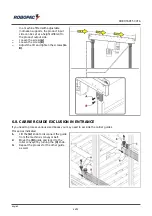
In a machine fitted with adjustable

inclination supports, the product input

side can be set at a height different to

the product output side.

Loosen the screw

(A)

.

Loosen the screw

(B)

.

Adjust the tilt and tighten the screws

(A -

B)

.

6.8. CARRIER GUIDE EXCLUSION IN ENTRANCE

If you need to process various sized boxes you may need to exclude the carrier guides.
Proceed as indicated.

1.

Lift the

(A)

knob to disconnect the guide

from the machine’s conveyor belt.

2.

Move the

(B)

guide and lock it to the

roller conveyor by turning the

(C)

knob.

3.

Repeat the process for the other guide

as well.

English

46/75

Summary of Contents for ROBOTAPE 50 CFA

Page 1: ...nslation of the original instructions Code 3709303011 0 Edition 1217 ____________ SERIAL NUMBER ____________ Caution Read and understand these instructions before using the machine Keep this handbook for further consultation ROBOPAC S p A ...

Page 2: ...IPTION 3 2 DESCRIPTION OF THE OPERATION CYCLE 3 3 SAFETY DEVICE DESCRIPTIONS 3 4 DESCRIPTION OF THE ELECTRICAL DEVICES 3 5 PNEUMATIC DEVICE DESCRIPTION 3 6 ACCESSORIES AVAILABLE UPON REQUEST 3 6 1 DESCRIPTION OF THE TAPING UNIT 3 7 TECHNICAL SPECIFICATIONS 3 7 1 MACHINE DIMENSIONS 3 7 2 TECHNICAL SPECIFICATIONS OF INFEED AND OUTFEED CONVEYORS OPTIONAL 3 7 3 SIZES OF CONVEYORS OPTIONAL 3 7 4 BOX DI...

Page 3: ...MAINTENANCE PERIOD TABLE 7 3 LUBRICATION POINT DIAGRAM 7 4 CONDENSATE DISCHARGE 7 5 CLEANING THE AIR FILTER 7 6 LUBRICANTS TABLE 8 TROUBLESHOOTING 8 1 TROUBLES CAUSES AND REMEDIES 8 2 ALARM MESSAGES 8 3 MESSAGES 9 SPARE PARTS REPLACEMENT INFORMATION 9 1 RECOMMENDATIONS FOR REPLACING PARTS 9 2 REPLACEMENT OF CONVEYOR BELT 9 3 HOW TO REPLACE THE TRANSPORT UNIT DRIVING CHAIN 9 4 CHANGE THE SIDE PRESS...

Page 4: ...cify the message Translation of the original instruction Keep this manual for the entire duration of its useful life in a well known and easy to access place available for reference any time the need should arise In order to easily consult the specific topics of interest check the table of contents Some information may not correspond completely to the actual configuration of the machine delivered ...

Page 5: ...ed technician a person authorised and chosen from those who have the requirements skills and information necessary for installation use and extraordinary maintenance of the machine Operator A person authorised and chosen from those who have the requirements skills and information necessary for installation use and ordinary maintenance of the machine Maintenance technician A person authorised and c...

Page 6: ...e agreement CE statement of conformity Warranty conditions included in this booklet Instructions for unpacking and installation Quick start guide Manuals of installed commercial devices if necessary for machine use USB flash drive that contains the information listed Use and maintenance manual translated into various languages Spare parts catalogue Wiring diagram and list of components 1 6 HOW TO ...

Page 7: ...rm them priorily on the type of work and the behaviour to be used The machine must be handled with the aid of specific means crane forklift etc by qualified personnel capable of observing the safety requirements When using the lifting means insert and or fasten the devices hooks forks etc ONLY into the points provided on the package and or the machine Transport the machine suitable means of adequa...

Page 8: ...resent unpredictable risks In order to minimise the risks related to assistants involvement you must inform them priorily on the type of work and the behaviour to be used Make sure that no foreign persons are present within the machine operating area during its production activity and maintenance Do not use the machine if the scheduled maintenance work has not been regularly carried out DO NOT con...

Page 9: ...nt workplace laws NEVER use the machine if the scheduled maintenance interventions have not been carried out accordingly DO NOT clean or wash the machine with aggressive products to avoid damaging the components DO NOT replace the components with non original spare parts or with different design and constructive features DO NOT leave the machine unattended at the end of the work without shutting i...

Page 10: ... CFA Danger of arms crushing do not put your hands inside the moving organs Danger of entanglement Do not get close to the conveying belts to avoid getting entangled with parts of the body or clothes English 10 75 ...

Page 11: ...ith current regulations on the matter Select the components according to the chemical and physical features of the material and carry out the differentiated waste disposal as per the standards in force Follow the procedures in this chapter Non compliance with the instructions given may cause risks for safety and health of the persons and economic damages 2 8 SAFETY WARNING FOR ELECTRICAL EQUIPMENT...

Page 12: ...dentified the power cut off switch F Information sign machine Start symbol G Mandatory sign it indicates the obligation to read the entire documentation before using the machine H Information sign it indicates the connection point for earthing the machine I Information sign it indicates the tension to be applied to the conveyor belt the adhesive is located inside the casing L Information signal ma...

Page 13: ...RROUNDING AREAS The illustration depicts the perimeter work areas of the machine A Operator s working area B Box loading unloading area C Sorrounding area D Electric power point E Compressed air connection point English 13 75 ...

Page 14: ...mm and 25 75 mm respectively available on the market The packs that contain liquids or insubstantial materials must be suitable for the product and must be perfectly closed and tight in order to prevent any leaks of the content It is equipped with a series of safety devices designed to avoid anyharm befalling the operator or other persons who come into contactwith the machine in any way The machin...

Page 15: ...e box leaned up during the taping G Electric panel H Flap closing device L Compressed air treatment adjustment unit M Fixed guards avoid access to the inner parts of the machine N Movable safety guards avoid access to the inner parts of the machine O Entrance carrier optional allows to transport and space the product to be taped consists of a motorized roller conveyor The carrier comes with guides...

Page 16: ... photocell 3 The b photocell detects the box the carriers if present stop the C conveyor belts automatically adapt to the width of the box to be taped and begin to move the box on 4 The box moves forward and activates the c photocell the carriers and conveyor belts are stopped the bridge comes down and the conveyor belts are re started Once it meets photocell a the flap closure F comes down to clo...

Page 17: ...tape only the lower part of the box or let the box pass by without taping it 7 The F flap closing unit goes up automatically The box comes out of the tapes and meets the d unload photocell The side pressers open the lift bridge rises the tapes open 8 The operator picks up the box exiting the machine The cycle ends and the machine is ready to start a new one English 17 75 ...

Page 18: ...ed guard outside structure which prevents the operator accessing D E Interlocked mobile guard allows the operator to access the interior of the operating area It is a door associated with an electric interlock device Upon opening the machine stops immediately Its restart is only possible upon closing of the door and restoring of the cycle F General exhaust solenoid valve closes the compressed air ...

Page 19: ...ects the passage of the product and commands the closure of the conveyor belts H Downward bridge photocell detects the passage of the product and commands the descent of the lifting bridge I Bridge up sensor detects the complete lifting of the lifting bridge J Bridge down limit switch detects the descent of the lifting bridge on the product K Upper head tape deficiency photocell detects that the t...

Page 20: ...re gauge 3 Solenoid valves bank Solenoid valve To eliminate the pneumatic pressure inside the machine in case of an emergency Stop Solenoid valve activates the up down bridge lift actuator Solenoid valve activates the bridge lift brake actuator Solenoid valve activates the stopper device actuator Solenoid valve activates the tape opening closure actuator Solenoid valve activates the tape brake act...

Page 21: ...e accessories listed below A Out feed product conveyor L 1000 W 500 B1 Feet for height adjustable carriers B2 Feet for height and tilting adjustable carriers C Casters D Taping units T50 T75 T75 30 E Conveying unit increase in height H 75 mm F Motorized product entrance carrier with self centring L 1000 W 500 system Single phase motor 230V 50Hz English 21 75 ...

Page 22: ...kg Supply voltage Standard 400V 3Ph 50Hz N T Installed power 0 4 kW 0 6 kW Conveyor belts height Standard 50 mm Conveyor belts height Optional 75 mm Ambient operating temperature 0 40 C Protection grade Electrical system IP 54 Protection grade Electric motors IP 54 Operating pressure pneumatic system 6 1 bar 0 6 1 MPa Air consumption per cycle Pneumatic system 8 Nl Consumption air min Pneumatic sy...

Page 23: ...ROBOTAPE 50 CFA 3 7 1 MACHINE DIMENSIONS Description Value mm A 3382 B 1160 C 1515 D 796 E 3656 F min 570 max 675 F Optional min 750 max 855 With optional carriers English 23 75 ...

Page 24: ...the technical specifications of the conveyors Description Carrier Forward speed 20 m min Supply voltage 400V 3Ph 50Hz T Installed power 0 18 kW Ambient operating temperature 0 40 C Useful transport width 500 mm 3 7 3 SIZES OF CONVEYORS OPTIONAL Description Value mm A 1000 B 500 C 562 D 562 E 892 F 443 English 24 75 ...

Page 25: ...ype of adhesive tape used Description Lm dB A Lw dBw A Lw mW A Lop dB A Lpf dB Empty operation xx x xx x xx x xx x Functioning in working conditions xx x xx x xx x xx x 77 6 Lm Average level of pressure on the measurement surface Lw Acoustic power output Lop Level at the operator s place Lpf Surface sound pressure level xx x Values being determined i Caution Warning Prolonged exposure over 80 dB A...

Page 26: ...e degree of humidity is not unpleasantly high low from the point of view of the operator A sufficient lighting in order that a pleasant relaxing working environment is created for the operator a boundary area that must be left around the machine for safety rea sons See surrounding areas a flat surface steady and without vibrations with adequate weight supporting capacity also in consideration of t...

Page 27: ...he machine and or the package Provide suitable safety conditions in compliance with the regulations on workplace safety to prevent and minimise the risks Pay attention to the SAFETY WARNINGS do not use the machine for UNSPECIFIED PURPOSES and assess the possible RESIDUAL RISKS 4 2 PACKAGING AND UNPACKING The packing is realised keeping the overall dimensions low also in consideration of the transp...

Page 28: ...adequately anchor the machinery to the means of transportation Important For further transportation recreate the initial packaging conditions for transport and handling The machine can be handled with a fork or hook lift truck having adequate capacity Position a lifting device as indicated in the figure i Caution Warning Before lifting the machine check for centering position of the load Cardboard...

Page 29: ...ROBOTAPE 50 CFA Packaging on pallet with protective nylon Only carriers without packaging English 29 75 ...

Page 30: ...ps to be taken to install dismantled parts Proceed as indicated 1 Lift the machine See transport and handling 2 If necessary identify the exact position and trace the co ordinates to correctly place the machine 3 Install the movable and fixed guards English 30 75 ...

Page 31: ...pped with swivel wheels F screw them onto the feet 5 Install the two taping units if necessary Block the top taping unit by lowering the stopper G Remove the protection caps A on blades B i Danger Warning The blade is very sharp English 31 75 ...

Page 32: ...Operate screws E to move feet D and level the machine see setting the workbench height 7 If machine is supplied with casters block them 8 Connect the product entrance carrier to the machine via the L socket English 32 75 ...

Page 33: ...e steps to be taken to install dismantled parts Proceed as indicated 1 Install the supports A B using the screws C I Caution Two operators are needed to perform the following operations 2 Remove the blocks used for transportation and stand the carrier up English 33 75 ...

Page 34: ...identify the exact position and trace the co ordinates to correctly place the machine 4 Lift the machine as shown and position it 5 Operate screws D to move feet E and level the machine see setting the workbench height English 34 75 ...

Page 35: ...OTAPE 50 CFA 6 Secure the carriers to the machine using the F G brackets and the screws provided 7 If included install the output carton stop plate C using the brackets D and screws supplied English 35 75 ...

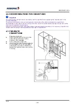
Page 36: ... all the statutory and legislation requirements Once the connection has been completed before commissioning the machinery it is necessary to perform an overall control to verify if said requirements have been complied with 4 7 PNEUMATIC CONNECTIONS Proceed as indicated 1 Insert a flexible tube on the end of the rubber fitting and fasten it with a metallic screw clamp A 2 Turn on the power supply l...

Page 37: ... main switch P to pos O 3 Connect the power cord to the outlet A as illustrated according to the network mains 4 The earth wire yellow and green must be connected to its earth terminal PE 5 Turn main switch P to pos 1 6 Start the electric motor and check that rotation direction is that indicated on the plate Important If the direction is wrong deactivate the main electrical knife and invert the ph...

Page 38: ...ctivated produce unexpected danger conditions provoking hazards to personal safety and health 5 2 CONVEYOR BELT ADJUSTMENT Proceed as indicated 1 Deactivate the main electric switch to put the machine in safety conditions 2 Remove transmission cover A 3 Loosen the nuts C 4 Operate nuts B to set the tension of the tape D Tighten or loosen screws B by the same degree to keep the alignment Important ...

Page 39: ...ng the machine check that no tools or other equipment has been left near the moving parts 5 4 ADJUSTMENT FLAP CLOSER DEVICE Proceed as indicated 1 Deactivate the main electric switch to put the machine in safety conditions 2 Loosen the screws G 3 Adjust the height and the width of the flap closing device and tighten the screws G i Caution Warning Before re starting the machine check that no tools ...

Page 40: ...c switch to put the machine in safety conditions 2 Remove transmission cover A 3 Loosen the nuts B 4 Move the motor unit to adjust the roller chain tension C 5 Tighten the nuts B i Caution Warning Before re starting the machine check that no tools or other equipment has been left near the moving parts English 40 75 ...

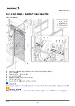
Page 41: ...sion cover B 4 Loosen the nuts C 5 Operate nuts D to adjust chain tension 6 Tighten the nuts C 7 Reassemble the B cover and close door A Important To check chain tension use the method indicated in the illustration The resulting shift 5 mm should be R i Caution Warning Before re starting the machine check that no tools or other equipment has been left near the moving parts English 41 75 ...

Page 42: ... used to stop with a voluntary action in case of imminent risk the organs of the machine that may pose a rick For further details consult the paragraph Description of safety devices C White pilot light when on indicates that the machine is electrically powered D Green Start button used to activate the machine s work cycle E Red Stop button used to stop the machine s work cycle F Cycle By Pass sele...

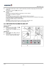
Page 43: ...ight indicates that the machine is still waiting for the outgoing boxes to be removed too full when exiting Lit flashing indicates the tape is almost finished Green light On steady it means that the machine is running in active automatic cycle Off indicates that the machine is NOT in active automatic cycle 6 3 SWITCHING THE MACHINE ON AND OFF Proceed as indicated Switching on 1 Turn the master swi...

Page 44: ...be released to authorize the machinery to restart 3 Restart the machine and check that it functions correctly see Switching the machine on and off 6 5 FORMAT CHANGE Before starting to operate with different features with respect to previous ones you must perform some adjustments on the machine The interventions which may be performed are indicated as follows Height setting of work table Carrier gu...

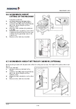
Page 45: ...ng legs and check that the value indicated on the gradutaed scale is the same for all 5 Make sure the machine is levelled 6 7 WORKBENCH HEIGHT SETTING OF CARRIERS OPTIONAL Before starting to work with characteristics different to the previous ones the height of the work surface must be set Proceed as indicated 1 Lift the machine as indicated in the figure 2 Loosen screws U adjust supporting leg V ...

Page 46: ...st the tilt and tighten the screws A B 6 8 CARRIER GUIDE EXCLUSION IN ENTRANCE If you need to process various sized boxes you may need to exclude the carrier guides Proceed as indicated 1 Lift the A knob to disconnect the guide from the machine s conveyor belt 2 Move the B guide and lock it to the roller conveyor by turning the C knob 3 Repeat the process for the other guide as well English 46 75 ...

Page 47: ...ntions but dispose them according to the standards in force Before performing any maintenance operation disconnect the power supply 7 2 MAINTENANCE PERIOD TABLE Important Keep the machinery in maximum efficiency condition and perform all the scheduled maintenance operations provided for by the manufacturer Proper maintenance will provide the best performance a longer life span and constant complia...

Page 48: ... conveyor belt replacement Every 1000 hours Cutting blade General inspection Check efficiency and if necessary replace See blade replacement iDanger Warning The blade is very sharp Every 2000 hours Transport unit driving chain General inspection Check for wear and if necessary replace See how the replace the driving chain of the transport unit Every 2000 hours Safety devices Efficiency control Rep...

Page 49: ...rication frequency to get top machine performances and a longer operating life Use lubricants oils or grease recommended by the manufacturer or with similar chemical physical features 7 4 CONDENSATE DISCHARGE Proceed as indicated 1 Close the pneumatic supply and check the formation of condensation in the cup A 2 Push the valve B up until all condensation is removed 3 Reactivate the pneumatic suppl...

Page 50: ...or Mineral oil 32 C 50 C 460 CST 40 C MELLANA OIL 460 IP SPARTAN EP 460 ESSO BLASIA 460 AGIP MOBILGEAR 634 MOBIL OMALA EP 460 SHELL ENERGOL GR XP 460 BP Worm gear motor Grease TELESIA COMPOUND B IP STRUCTOVIS P LIQUID KLUBER TOTALCARTER SYOO TOTAL Gear and worm gear motor Synthetic oil TELESIA OIL IP SYNTHESO D 220 EP KLUBER BLASIA S 220 AGIP Gear and worm gear motor Lithium grease ALVANIA R2 SHEL...

Page 51: ...ioning during processing the machine stops automatically Important For these operations a precise technical skill or ability is required therefore these operations must be exclusively performed by qualified personnel with certified experience acquired in the specific field Warning Cause Signalling on column Remedy EMERGENCY ALARM MUSHROOM BUTTON PRESSED Emergency alarm mushroom button pressed Red ...

Page 52: ... The tapes are not opening Red light 4 flashes Check the pressure in the pneumatic system Press the Start button BRIDGE NOT DOWN WARNING The bridge can t reach the downward position Red light 5 flashes Press the STOP button Check the pressure in the pneumatic system Press the Start button FLAP COVER PHOTOCELL ALARM ENGAGED The flap closure photocell doesn t free itself during the taping of the pro...

Page 53: ...olumn Remedy TOO FULL IN OUTFEED AREA The output photocell is not free Yellow light constantly on Remove the outbound products TAPE ALMOST FINISHED The tape is running out Yellow light continuous flashing Get ready to change the tape English 53 75 ...

Page 54: ...anger conditions provoking hazards to personal safety and health When replacing worn parts use only original replacement parts The Manufacturer is not responsible for any damage to property or injuries to people caused by the use of non genuine spare parts or which may result from repairs not authorised by the Manufacturer When ordering new parts follow the instructions given in the spares catalog...

Page 55: ...ely 3 Remove the chain links T and remove chains R 4 Install the new chains and lock them with the chain links 5 Adjust chain tension See how the adjust the driving chain of the transport unit 6 Carry out the operation on both driving units Important Replace one chain at a time to avoid misalignment of conveyor belts in relation to taping head 7 Restart the machine and check that it functions corr...

Page 56: ...t no tools or other equipment has been left near the moving parts 9 5 LIST OF THE RECOMMENDED SPARE PARTS List of the spare parts of easy wear and of which it would be necessary to have available to avoid long operation stops of the machine For ordering contact your local Dealer and refer to the spare parts catalogue N 1 main spring of bottom taping unit N 1 main spring of top taping unit N 2 cutt...

Page 57: ...s Useful information for the disposal of machines and machine parts Scrapping must be performed by qualified personnel Construction material Low density linear polyethylene L L D PE Steel aluminium and cast iron Copper and silver in the electrical electronic components Rubber resins and fibres None of the component materials is harmful or poisonous Special care must be taken when disposing of left...

Page 58: ...losses due to lack of production or injuries to persons or damage to things caused by malfunctions or forced suspension in using the machine covered by the warranty THE WARRANTY DOES NOT COVER damage caused by transport damage due to incorrect installation improper use of the machine or negligence tampering or repairs by unauthorised personnel lack of maintenance parts subject to normal wear and t...

Page 59: ...ATIC CIRCUIT DIAGRAM Key A Air treatment unit B Solenoid valve C Solenoid valve D Solenoid valve E Pneumatic cylinder F Pneumatic cylinder G Pneumatic cylinder H Pneumatic cylinder L Pneumatic cylinder M Regulator English 59 75 ...

Page 60: ...ROBOTAPE 50 CFA 10 3 T50 T75 T50 30 TAPING UNIT OPERATING MANUAL The following are instructions for use provided directly by the manufacturer English 60 75 ...

Page 61: ...T50 T75 T50 30 ROBOTAPE GB USE AND MAINTENANCE MANUAL Translation of the original instructions Taping unit English Edition 0 0115 61 75 ...

Page 62: ...62 75 ...

Page 63: ...3 2 2 Description of components 3 2 3 DIMENSIONS 4 5 Information on adjustments 5 1 Adjusting the taping unit 5 5 2 ADJUSTING THE FRONT FLAP LENGTH 6 6 About the use 6 1 MOUNTING THE TAPE 8 7 Maintenance information 7 1 REPLACING THE BLADE 10 7 2 Correcting taping errors 11 63 75 ...

Page 64: ...64 75 ...

Page 65: ...edisposed for such a unit It is also possible to adjust the length of the front flap as needed 1 Roll hub 2 Spring hooking rings 3 Knurled nonreturn roller 4 Return roller 5 Recovery roller 6 Tape shaper sheet 7 Tape contrast sheet 8 Infeed roller 9 Blade 10 Knurled transmission roller 11 Smooth transmission roller 12 Adjusting cam 13 Cut adjusting guide Note To be removed for 50 mm seams 14 Blade...

Page 66: ...75 T75 English Chapter 2 Technical information 2 3 DIMENSIONS Reel dimensions Max reel diameter 400 mm Internal roll holder pipe diamete 76 2 mm Width Mod T50 25 50 mm Mod T75 25 75 mm Types of adhesive tape PVC polypropylene PPL 66 75 ...

Page 67: ...s of the hand wheel A Loose roll holder for PVC Roll holder with slight friction for PPL Adjust the tension on the clutch controlled roller B by means of the screw C Clutch released for PVC Clutch slightly engaged for PPL Adjust the main spring Load the spring less for light boxes load the spring more for sturdy boxes 67 75 ...

Page 68: ... 6 3 3 English Chapter 5 Information on adjustments 5 2 ADJUSTING THE FRONT FLAP LENGTH 70 mm flap Arrange parts 1 2 3 as shown in the figure 50 mm flap Arrange parts 1 2 3 as shown in the figure 68 75 ...

Page 69: ... 7 English 7 Chapter 5 Information on adjustments 30 mm flap 69 75 ...

Page 70: ...ant Make sure the adhesive surface is in the correct position If installing a roll of 50 mm wide tape 2 on the T75 taping head you must also include a spacer A between the reel and the hub Glue the tape provided to the tape pull Insert the tape pull following the path shown on the plate Important The dashed line refers to the adhesive side of the reel Pull and cut off excess tape 70 75 ...

Page 71: ... 9 English 9 Chapter 6 About the use 70 and 50 mm flap 30 mm flap 71 75 ...

Page 72: ...uard A is not present on the T50 30 taping head 30 mm flap Loosen the screws B Remove the blade C Insert the new blade making sure the sharp side is correctly positioned Tighten the screws B Release the guard A Important Make sure the blade does not interfere with the guard before fastening it in place Danger Warning The blade is very sharp 72 75 ...

Page 73: ...k glue tapes it may be necessary to increase the braking effect on the roll holder roller and the first transmission roller Problem Tape curls Remedy Always Upper unit adjust the height of the upper head approximately 3 mm from the box Only if the error persists Upper and lower unit adjust the eccentric part A to change the position of the roller B approximately 2 mm underneath the slide surface o...

Page 74: ... 12 English Chapter 7 Maintenance information Problem Tape creases Remedy Make sure the rollers turn freely Make sure the friction on the roll holder is very slight 74 75 ...

Page 75: ...ROBOTAPE 50 CFA 10 4 CE STATEMENT OF CONFORMITY English 75 75 ...

Reviews: