RS-Helios-16P User Manual
11
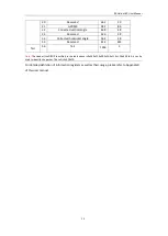
Table 5 Ranging Capability of LiDAR Channel
Channel No.
Vertical Angle
(
°
)
10% NIST
(
m
)
Range
(
m
)
1
13°
90
120
2
15°
90
120
3
9°
90
150
4
11°
90
120
5
5°
90
150
6
7°
90
150
7
1°
90
150
8
3°
90
150
9
-3°
90
150
10
-1°
90
150
11
-7°
90
150
12
-5°
90
150
13
-11°
90
120
14
-9°
90
150
15
-15°
90
120
16
-13°
90
120
5.2
Point Cloud Display
5.2.1
Coordinate Mapping
Since the data packet output by the LiDAR only provides the horizontal rotation angle and
distance parameters, in order to present a 3D point cloud image, the angle and distance
information in polar coordinates need to be converted into x, y, z coordinates in the Cartesian
coordinate system, and the conversion formula is as follows:
{
𝑥 = 𝑟 𝑐𝑜𝑠( 𝜔) 𝑠𝑖𝑛( 𝛼);
𝑦 = 𝑟 𝑐𝑜𝑠( 𝜔) 𝑐𝑜𝑠( 𝛼);
𝑧 = 𝑟 𝑠𝑖𝑛( 𝜔);
Where
𝑟
is the measured distance,
is the vertical angle of the laser,
is the horizontal
rotation angle of the laser in the Polar Coordinate System, and x, y, z are the coordinate values in
the Cartesian Coordinate System.
Note 1:
ROS source code of RS-Helios-16P has by default completed the coordinate conversion to conform to the
right-handed coordinate system of ROS. The X-axis of ROS is the positive Y direction in Figure 1, and the Y-axis of
ROS is the negative X direction in Figure 1.
Note 2:
The origin of the LiDAR sensor coordinate is
63.5
mm above the LiDAR base, on the center axis.


