background image

RS-Helios-1610 User Manual

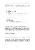
23

15

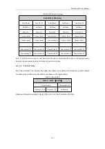
Web page cgi backup CRC

79

4

16

Ethernet gateway

83

4

17

Subnet mask

87

4

18

Reserved

91

201

19

Serial number

292

6

20

Zero angle offset

298

2

21

Return mode

300

1

22

Time Synchronization Mode

301

1

23

Synchronization status

302

1

24

Time

303

10

25

Operating status

313

12

26

Reserved

325

17

27

Fault diagnosis

342

18

28

Whether the code wheel is calibrated

360

1

29

GPS PPS pulse trigger mode

361

1

30

Reserved

362

20

31

GPRMC

382

86

32

Corrected vertical angle

468

96

33

Corrected horizontal angle

564

96

34

Reserved

660

586

Tail

35

Tail

1246

2

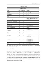
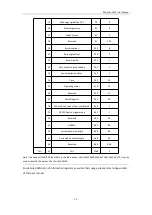
Note: The Header (the DIFOP identifier) in the table above is 0xA5,0xFF,0x00,0x5A,0x11,0x11,0x55,0x55, it can be
used to identify the packet. The tail is 0x0F,0xF0.

For detailed definition of information registers as well as their usage, please refer to Appendix B
of this user manual.

Summary of Contents for RS-Helios-1610

Page 1: ...RS Helios 1610 User Manual RS Helios 1610...

Page 2: ...RS Helios 1610 User Manual I Revision History Issue Modifications Release Date Edited by 1 0 0 Original issue 2022 08 31 PD...

Page 3: ...Protocol version number 00 represents old version 01 represents the latest version Temp Sensor temperature information Resv Reserved data flag Azimuth LiDAR horizontal rotation angle Timestamp Time st...

Page 4: ...2 Return Mode Flag 14 5 5 Phase Locking 14 5 6 Time Synchronization 15 5 6 1 GPS Time Synchronization 15 5 6 2 The Use of GPS for Time Synchronization 15 5 6 3 PTP Time Synchronization 16 5 6 4 PTP w...

Page 5: ...TC_TIME 39 B 14 STATUS STATUS 40 B 15 Fault Diagnosis FALT_DIGS 40 B 16 GPRMC Data Packet ASCII Code Data Type 42 Appendix C RSView 43 C 1 Software Features 43 C 2 Install RSView 43 C 3 Set Up Network...

Page 6: ...This manual is protected by copyright Any rights arising from this copyright are owned by RoboSense Reproduction of this manual or part of the manual is only permitted within the legal scope of the co...

Page 7: ...ase pay attention to the overheating sign on the LiDAR surface to avoid a hot LiDAR surface that may lead to sensor failure or undesirable consequences Retain Instructions The safety and operating ins...

Page 8: ...el Number of Channels FOV Remark 1 RS Helios 5515 32 55 15 Wide FOV 2 RS Helios 1615 32 16 15 Uniform 1 Vertical Resolution 3 RS Helios 1610 32 16 10 up to 0 5 4 RS Helios 16P 16 15 15 Uniform 2 Verti...

Page 9: ...tion RS Helios 1610 has an aviation plug attached to the bottom of the LiDAR the definitions of the specific pins of the aviation plug are as shown in the table below Pin Color Function Operating Volt...

Page 10: ...tact RoboSense technical support Figure 3 Definition of Interface Box Ports Specifications of Interface Box ports Table 1 Interface Box Port Specification No Port Specification 1 Power Input Standard...

Page 11: ...Box follows the EIA TIA568 standard 3 3 3 GPS Time Synchronization RS Helios 1610 uses GPS for Time Synchronization the GPS REC receives GPS UART standard input GPS PULSE receives GPS PPS information...

Page 12: ...0W 1 4 Power Cable 1 2M 1 5 Ethernet Cable 1 5M 1 6 Screw Pack M3X8 4 M3X12 4 Note There might be variants of the sensor and accessories that you are going to purchase or interested in please contact...

Page 13: ...nting Bracket Rigidity Requirements The mounting bracket where the LiDAR is attached to should be rigid enough to ensure LiDAR in a stable operating state under various working conditions Therefore it...

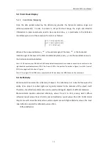
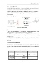
Page 14: ...the cables in a slack state 4 3 Quick Connection Users are allowed to configure the network settings of the RS Helios 1610 which is set at the factory with default IP and port numbers as shown in the...

Page 15: ...RS Helios 1610 User Manual 9 The wiring diagram of the Interface Box connection is as shown in the figure below Figure 6 Interface Box Connection Interface Box...

Page 16: ...s Time Stamps Mechanical Operating Voltage 9V 32V Dimension 97 5mm H100 mm Power Consumption4 12W Typical 20W Peak Operating Temperature5 30 to 60 1 The data above is only for serial production produc...

Page 17: ...16 10 50 150 32 7 50 150 14 5 90 150 30 3 5 90 150 31 3 90 150 7 2 5 90 150 12 2 90 150 23 1 5 90 150 15 1 90 150 28 0 5 90 150 29 0 90 150 5 0 5 90 150 10 1 90 150 21 1 5 90 150 13 2 90 150 26 2 5 9...

Page 18: ...the right handed coordinate system of ROS The X axis of ROS is the positive Y direction in Figure 1 and the Y axis of ROS is the negative X direction in Figure 1 Note 2 The origin of the LiDAR sensor...

Page 19: ...ctions RS Helios 1610 analyzes the received multiple returns and can be set to only report the strongest return first return or the last return each time in the single return mode or report the strong...

Page 20: ...to Appendix A 2 of this user manual for instructions The 300th byte in a DIFOP packet is the flag of return mode which corresponds to the following Table 6 Return Mode Flag Flag Return Mode 00 Dual Re...

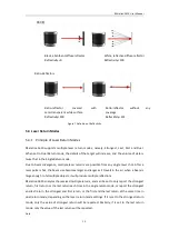
Page 21: ...ation Timing Diagram The GPS module continuously sends GPRMC message and PPS synchronization pulse signals to the sensor The PPS synchronization pulse width is from 20ms to 200ms and the GPRMC message...

Page 22: ...RMC message must be A valid before time synchronization is allowed 3 The length of GPRMC messages sent by existing GPS modules on the market is not consistent The length of GPRMC messages reserved in...

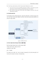
Page 23: ...t by the PTP Master and does not make accuracy judgments If the time of the LiDAR deviates from the real time please check whether the time provided by the PTP Master is accurate 3 After the LiDAR is...

Page 24: ...ate LiDAR to the computer 6 1 MSOP and DIFOP The UDP packet sent by RS Helios 1610 has a payload of 1248 bytes the data structure of the main data stream output protocol MSOP and device information ou...

Page 25: ...ata has 3 bytes corresponding to a firing sequences of the 32 lasers channel data 1 to channel data 32 Please refer to Section 6 of this manual for the relationship between channel number and vertical...

Page 26: ...ata 31 Channel data 31 Channel data 32 Channel data 32 Channel data 32 Channel data 32 Channel data 32 Note In the dual return mode for each data block the odd numbered data block reports the stronges...

Page 27: ...azimuth based on azimuth data in the data packet 1 Find the azimuth value in the data packet and convert to a hexadecimal number 0x88 0xdb 2 Convert to a 16bit unsigned integer 0x88db 3 Convert to a d...

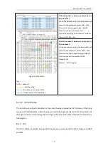
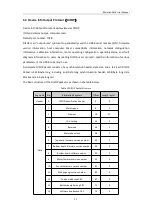
Page 28: ...consists of a synchronization header data area and a tail Each DIFOP Packet is 1248 byte long including an 8 byte long synchronization header 1238 byte long data blocks and a 2 byte long tail The bas...

Page 29: ...ault diagnosis 342 18 28 Whether the code wheel is calibrated 360 1 29 GPS PPS pulse trigger mode 361 1 30 Reserved 362 20 31 GPRMC 382 86 32 Corrected vertical angle 468 96 33 Corrected horizontal an...

Page 30: ...equired to complete one round of firing and recharging of 32 lasers is 55 56us In each MSOP Packet there are 12 data blocks and each data block stores measurements of 1 firing sequences of 32 lasers t...

Page 31: ...RS Helios 1610 User Manual 25 Table 13 MSOP Packet Time Offset of Exact Laser Point Timing in Single Return Mode Table 14 MSOP Packet Time Offset of Exact Laser Point Timing in Dual Return Mode...

Page 32: ...no data output Check whether the network connection is normal Check whether the computer network configuration is correct Use another software such as wireshark to check whether the packet output is n...

Page 33: ...e the same ground Make sure that the GPS has received valid message Make sure that the GPS module is outdoors Check if the PTP Master synchronization protocol complies with the current PTP protocol Ch...

Page 34: ...omputer browser to access the LiDAR IP address default Device IP 192 168 1 200 and enter the LiDAR web homepage the homepage defaults to the Device page A 1 Device Screen After accessing the LiDAR Web...

Page 35: ...to 65535 3 The Return Mode has four options Strongest default Last First and Dual 4 The FOV can be set from 0 to 360 when set only the point cloud of the set FOV will be output 5 The sensor rotation s...

Page 36: ...nd the SYNC_OUT2 pin but the Interface Box has reserved only the SYNC_OUT1 pin Please refer to Table 2 GPS Port Definition for more details Therefore only First Group is available and the Second Group...

Page 37: ...Screen of the Web Interface Description 1 Voltage Monitor shows the voltage of the sensor input power supply in real time When the LiDAR Operation Mode is set in the Standby mode the input box will t...

Page 38: ...Board Firmware Update as an example is as shown below 1 Prepare the Top Board firmware that is going to be used for the update Click the Choose File button to navigate to the folder where the new TOP...

Page 39: ...de package name must meet the following requirements before it can be upgraded normally otherwise an error will be reported Top board upgrade file The necessary prefix helios_top The necessary suffix...

Page 40: ...H 22 bytes in total Byte No byte1 byte2 byte3 byte4 byte5 byte6 byte7 byte8 Function LIDAR_IP DEST_PC_IP Byte No byte9 byte10 byte11 byte12 byte13 byte14 byte15 byte16 Function MAC_ADDR port1 Byte No...

Page 41: ...ations bytes have been converted from hexadecimal to decimal B 4 Motor Phase Offset MOT_PHASE MOT_PHASE 2 bytes in total Byte No byte1 byte2 Function MOT_PHASE Register description This register can b...

Page 42: ...ersion 01030100 B 7 Motor Firmware Version MOT_FRM MOT_FRM 5 bytes in total Byte No byte1 byte2 byte3 byte4 byte5 Function MOT_FRM Register description This register corresponds to the motor firmware...

Page 43: ...ion Channel 16 vertical angle Channel 17 vertical angle Channel 18 vertical angle Byte No byte55 byte56 byte57 byte58 byte59 byte60 byte61 byte62 byte63 Function Channel 19 vertical angle Channel 20 v...

Page 44: ...tal angle Channel 12 horizontal angle Byte No byte37 byte38 byte39 byte40 byte41 byte42 byte43 byte44 byte45 Function Channel 13 horizontal angle Channel 14 horizontal angle Channel 15 horizontal angl...

Page 45: ...s 1 byte3 0x96 converted to decimal is 150 then the vertical angle of channel 1 is 1 256 150 0 01 4 06 B 11 Serial Number SN SN 6 bytes in total Byte No 1byte 2byte 3byte 4byte 5byte 6byte Function SN...

Page 46: ...st and the low order last Register description 1 Idat is the current of the LiDAR power supply The current value is composed of 2 bytes Current calculation formula Idat Value_temp 4096 5A For example...

Page 47: ...a Temperature2 3 4 200 value 4096 50 temperature1 temperature5 are the temperature of the top board bottom board FPGA chip respectively The temperature value is composed of 2 bytes and the calculation...

Page 48: ...s follows Motor real time speed value For example when byte32 0x58 byte33 0x02 r_rpm 0x0258 600rpm 4 Other registers are used for internal debugging B 16 GPRMC Data Packet ASCII Code Data Type 86 byte...

Page 49: ...LAS format point cloud files while the previous versions of RSView do not support generating point cloud files in LAS XYZ or PLY formats Functionality and features of RSView include Visualize live str...

Page 50: ...ualize Streaming Sensor Data 1 Connect LiDAR to power and connect to computer by network cable 2 Right Click to start the RSView application with Run As Administrator 3 Click on File Open and select S...

Page 51: ...w will start to write the packet file into the target pcap file Note RS Helios LiDAR will generate huge volume of data As the recording time gets longer the target pcap file will become larger Therefo...

Page 52: ...C 7 Open Recorded pacp File 3 In the pop up Sensor Configuration dialog add and select the correct RS Helios configuration file and click the OK button 4 Click the Play button to play or pause the dat...

Page 53: ...ng to the selected points Figure C 11 Figure C 11 RSView Show only selected elements Tool 8 Click the Select All Points tool which turns your mouse into a data point selection tool Figure C 12 Figure...

Page 54: ...ed in the means described in Section C 7 in other ways you will need to reset the Data Port that RSView acquires data to the modified port number otherwise there will be no data display If you don t k...

Page 55: ...k or contact our technical support to get it After downloading please read the README file in the driver package carefully which describes in detail how to compile and use the LiDAR driver package rsl...

Page 56: ...192 168 1 102 the subnet mask to 255 255 255 0 The gateway does not need to be configured After the configuration is completed you can use the ifconfig command to check whether the static IP takes ef...

Page 57: ...e is just a brief introduction taking pcap as an example You can use rslidar_sdk to parse the saved offline pcap file into point cloud data for display 1 Modify the parameters in rslidar_sdk config co...

Page 58: ...RS Helios 1610 User Manual 52 Appendix E Mechanical Drawings...

Page 59: ...ed to the surface of the sensor you can directly dip a small amount of isopropanol solution with a clean fiber cloth and then gently wipe the LiDAR surface to clean and then wipe it dry with a clean f...

Page 60: ...RS Helios 1610 User Manual...

Reviews: