Robotiq Finishing Kits- Instruction Manual
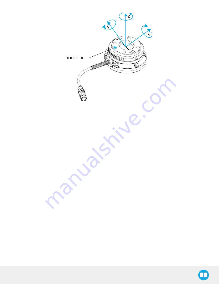
Fig. 1-2: FT 300-S Force Torque Sensor force and torque diagrams.
The figure above represents the various forces and torques that the FT 300-S Force Torque Sensor can measure. Reference frame
is centered on the Sensor as shown above and visual inscriptions are also represented on it.
l
The Z axis passes through the center of the depression with positive direction in the tool direction.
l
The X axis traces a symmetric line centered on the connector; the positive direction points the opposite way away from the con-
nector.
l
The Y axis uses the right hand thumb rule according to X-Z.
8


