AirPick - Instruction Manual
Caution
It is the robot integrator’s responsibility to ensure that all local safety measures and regulations are met.
The following non-exhaustive list presents risks that must be assessed during the integration process:
l
Risk of contact between body parts and suction cups during gripping;
l
Risk of load ejection resulting from loss of vacuum;
l
Risk of load dropping resulting from loss of vacuum;
l
Risk of pinching between the Vacuum Gripper and the part(s) or the environment;
l
Risk of damage or breaking if using a custom suction cup bracket that does not meet the technical requirements.
Depending on the application, there may be hazards that require additional protection and/or safety measures. For instance, the
workpiece handled by the Gripper could be inherently dangerous to the operator.
Warning
Depending on the supply sources, when an emergency stop (e-Stop) button is pressed, the following consequences may
occur. The robot owner has the responsibility to do a risk assessment and choose the appropriate option.
Supply sources
e-Stop consequences
Robot tool supply
(tool connector)
Power failure to the Vacuum Gripper. The vacuum level will drop to ambient pressure and
the object will be lost.
Robot controller supply
(Any 24V pin)
Vacuum Gripper powered ON.
l
If an object is detected: the vacuum level will continue to be regulated and the object
will not be lost.
l
If no object is detected: the Vacuum Gripper will go into a standby state 2 seconds
after the e-Stop button is pressed.
Warning
Loss of vacuum can occur due to power failure or air supply interruption.
2.2. Intended Use
The Gripper unit is designed for gripping and temporarily securing or holding objects.
Caution
The Gripper is NOT intended for applying force against objects or surfaces.
12
Summary of Contents for AirPick
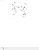
Page 25: ...Fig 3 7 Mounting air nodes suction cups air bolts air nuts on the bracket 25...
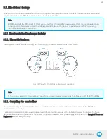
Page 27: ...Fig 3 9 Robotiq Vacuum Gripper with pigtail cable and device cable wiring scheme 27...
Page 35: ...Fig 4 1 Vacuum Gripper control logic overview 35...
Page 57: ...7 Click on the New Project icon in the upper left corner of the screen 57...
Page 58: ...AirPick Instruction Manual 8 Enter a name for your program and click on the OK button 9 58...
Page 76: ...Fig 6 5 Minimum and maximum arrangement possibilities of the air nodes position 76...
Page 77: ...AirPick Instruction Manual 6 1 3 Air nodes Fig 6 6 Air nodes dimensions 77...
Page 103: ...AirPick Instruction Manual 12 Appendix Fig 12 1 Pneumatic schema of the AirPick Vacuum Gripper...


