AirPick - Instruction Manual
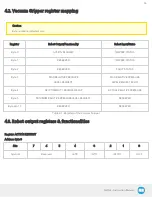
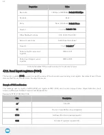
4.2. Vacuum Gripper register mapping
Caution
Byte numbering starts at zero.
Register
Robot Output/Functionality
Robot Input/Status
Byte 0
ACTION REQUEST
GRIPPER STATUS
Byte 1
RESERVED
GRIPPER STATUS
Byte 2
RESERVED
FAULT STATUS
Byte 3
MAX RELATIVE PRESSURE
LEVEL REQUEST
MAX RELATIVE PRESSURE
LEVEL REQUEST ECHO
Byte 4
GRIP TIMEOUT / RELEASE DELAY
ACTUAL RELATIVE PRESSURE
Byte 5
MINIMUM RELATIVE PRESSURE LEVEL REQUEST
RESERVED
Byte 6 to 15
RESERVED
RESERVED
Table 4-1: Registers of the Vacuum Gripper
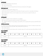
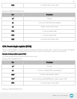
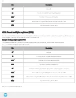
4.3. Robot output registers & functionalities
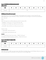
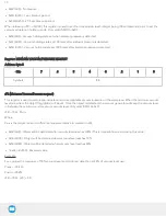
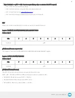
Register: ACTION REQUEST
Address: Byte 0
Bits
7
6
5
4
3
2
1
0
Symbols
Reserved
rATR
rGTO
rMOD
rACT
36
Summary of Contents for AirPick
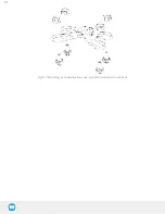
Page 25: ...Fig 3 7 Mounting air nodes suction cups air bolts air nuts on the bracket 25...
Page 27: ...Fig 3 9 Robotiq Vacuum Gripper with pigtail cable and device cable wiring scheme 27...
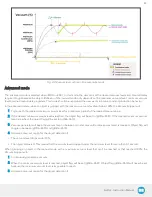
Page 35: ...Fig 4 1 Vacuum Gripper control logic overview 35...
Page 57: ...7 Click on the New Project icon in the upper left corner of the screen 57...
Page 58: ...AirPick Instruction Manual 8 Enter a name for your program and click on the OK button 9 58...
Page 76: ...Fig 6 5 Minimum and maximum arrangement possibilities of the air nodes position 76...
Page 77: ...AirPick Instruction Manual 6 1 3 Air nodes Fig 6 6 Air nodes dimensions 77...
Page 103: ...AirPick Instruction Manual 12 Appendix Fig 12 1 Pneumatic schema of the AirPick Vacuum Gripper...

