Wiring
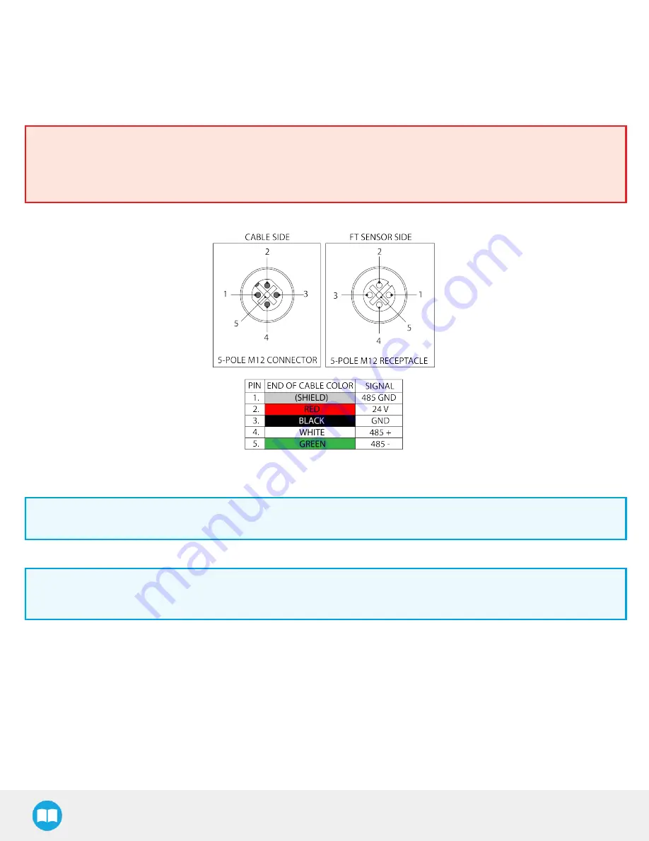
Power and communications are established with the FT 300 Force Torque Sensor via a single device cable. The FT 300 has a pigtail
cable. The figure below represents the FT 300 Force Torque Sensor receptacle (Sensor side) and connector (cable side) with associated
pinout. The M12 - 5 pin A-coded connector is used in accordance with IEC 61076-2-101.
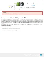
Warning
Use proper cabling management. Be sure to have enough forgiveness in the cabling to allow movement of the Gripper along
all axes without pulling out the connectors. Always protect the controller side of the cable connection with a strain relief cable
clamp.
Fig. 3-5: Pinout of the Robotiq Force Torque Sensor FT 300 and color code for the respective cable type.
Info
Power pins 2 & 3 are connected to the specified power supply.
Info
RS-485 signal pins 1, 4 & 5 are connected directly, to a RS-485 / USB converter or to a RS-485 / RS-232 converter.
Wiring with USB to RS485 Converter
When using a RS485 to USB converter, the wiring must respect the figure below and subsequent directions. GND / 0V is wired to Sensor
pin #1 as stated in the Installation section.
The converter will provide you with a standard USB 2.0 male A connector.
22


