background image

External Tool Finishing Kit - Instruction Manual

4

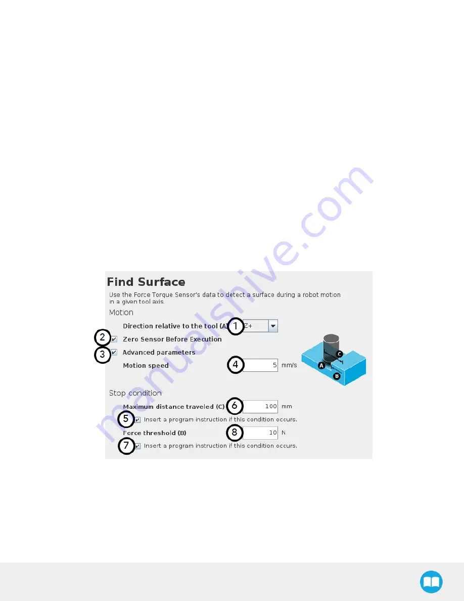
Speed parameter: Textbox for the user to enter a speed value for the approach motion towards the destination

5

Force threshold parameter: Textbox for the user to enter a force threshold value that completes the linear motion

6

Maximum travel distance (Error condition): Textbox for the user to enter the maximum distance value which, upon being reached,
means the force threshold has never been reached in the linear motion

4.2.9. Find Surface Node

The Force Copilot software package includes the Find Surface node, which is a great tool for machine tending and various other
applications that require repeated accurate positioning of objects.

The default parameters of the function allow for a versatile demo or a quick test of the features while the advanced parameters make it
a more customizable asset.

How to add a Find Surface node

l

On the teach pendant, tap the New button to create a program or the Open button to load a program

l

Tap the URCaps button in the navigation pane on the left

l

Select Find Surface

l

Tap the Find Surface node in the robot program to edit it

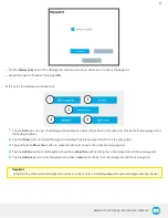
1

Direction relative to the tool drop-down menu: Menu used to select the direction of the linear motion, relative to the tool

2

Zero Sensor Before Execution box: Box that inserts a Zero FT Sensor command right before the Find Surface instructions

3

Advanced parameters box: Box that expands the advanced parameters menu when ticked

4

Motion speed parameter: Textbox for the user to enter a speed value for the approach motion towards the destination

81

Summary of Contents for ETF-CB-UR-KIT

Page 1: ...Robotiq External Tool Finishing Kit on Universal Robots Instruction Manual robotiq com leanrobotics org Original Notice 2019 Robotiq Inc...

Page 2: ...sand Equipment 16 3 3 Environmentaland Operating Conditions 16 Hand E Gripper 16 FT Sensor for CB Series robots 17 3 4 MechanicalInstallation 17 3 4 1 Installing the fingers fingertips holders on the...

Page 3: ...Series robots 37 Features 38 Gripper operation window 40 4 1 4 Gripper Node 41 Command window 42 Features 43 Edit action screen 45 Features 45 Grip Check node 47 On e Series 47 On CB Series 47 About 4...

Page 4: ...8 Insertion nodes 76 Child nodes 77 Features Spiral 77 Features Rotational 79 Features Linear 80 4 2 9 Find Surface Node 81 4 2 10 Force Control node 83 Overview 83 Features 83 Reference frame 83 Para...

Page 5: ...1 Maximum payload External force vs Custom finger design 102 Friction grasp and form fit grasp 104 Maximum payload by grasp type 104 5 2 3 Center of mass and tool center point of the FT Sensor and the...

Page 6: ...ot be reproduced in whole or in part whether for sale or not without prior written consent from Robotiq Under copyright law copying includes translation into another language or format Information pro...

Page 7: ...uses a point on the external tool as a reference to measure wear With 0 2 mm precision contact offset validates the tool s exact position anytime you wish If there s a slight change the robot program...

Page 8: ...how to integrate custom fingers and fingertips to Hand E Fig 1 2 Mounting a finger on a rack When ordered as a kit a fingertip starting kit is included Please refer to the Spare Parts Kits and Access...

Page 9: ...1 3 Setup and Control The Hand E Gripper has an embedded object detection feature based on indirect sensing methods When picking an object with the go to command the gripper status indicates whether o...

Page 10: ...le a USB storage device hosting the product license The Finishing Copilot software is used for the implementation of a force torque sensor s operational commands in a user interface and that unlocks f...

Page 11: ...ings l M12 connector pigtail or mounted allows for both power and data transfer for the Sensor l Status LED provides visual information on the status of the Sensor see StatusLED sectionof the FT 300 F...

Page 12: ...s l SensorCable is used for power and communications with the FT 300 Force Torque Sensor and is available in different lengths l Mechanical Protectoris meant to protect the cable connector from collis...

Page 13: ...e Gripper needs to be properly secured before operating the robot l Do not install or operate a Gripper that is damaged or lacking parts l Never supply the Gripper with an alternative current source l...

Page 14: ...e on our website www robotiq com or contact our technical support 2 1 2 Intended Use For the Hand EGripper The Gripper unit is designed for gripping and temporarily securing or holding objects Info Al...

Page 15: ...nchored and the danger zone is cleared l The fingers of the Hand E Gripper may move and cause injury or damage 3 1 Scope of delivery of the External Tool Finishing Kit for UR ETF ES UR KIT Included in...

Page 16: ...ions Hand EGripper Caution Use of the Hand E Gripper is not recommended in presence of chemicals in the environment Conditions Value Minimum storage transit temperature 30 C 22 F Maximum storage trans...

Page 17: ...sing 20 80 RH Maximum vibration storage transit 5G Maximum vibration operating 2G IP rating IP 40 Other l Free from dust soot or water l Free from corrosive liquids or gases l Free from explosive liqu...

Page 18: ...Fig 3 1 Mounting fingers on racks Fig 3 2 Mounting fingertips on holders and then on racks 18...

Page 19: ...he Hand E on the robot exploded view in the figure below Note that all screws should be locked using medium strength threadlocker 1 Mount the coupling on the robot tool flange Align using the dowel pi...

Page 20: ...ory you can customize yours from a blank provided by Robotiq Here are the steps to follow for the installation of the Sensor see figure below Note that all screws must be locked in place using medium...

Page 21: ...use the 24 Volt external source available on the CB Series controller POWERSUPPLY SPECIFICATIONS VALUE Output voltage 5 to 24 V DC Max power consumption 2 W Overcurrent 1 A Fuse Phoenix 0916604 UT6 T...

Page 22: ...ithout pulling out the connectors Always protect the controller side of the cable connection with a strain relief cable clamp Fig 3 5 Pinout of the Robotiq Force Torque Sensor FT 300 and color code fo...

Page 23: ...ate a custom version for you Some couplings may require an additional adapter plate To create your own coupling and or adapter plate and to see the details of the available couplings and adapter plate...

Page 24: ...Robotiq provides you with a Universal Robots URCap package that enables direct serial communication to your UR controller The External Tool Finishing Kit URCap installation consists in the installati...

Page 25: ...ller is compatible with the package refer to the Installation section Info Use the latest Polyscope version with your Finishing Copilot to ensure compatibility Make sure your Finishing Copilot is up t...

Page 26: ...hen Universal Robots l Click on Software External Tool Finishing URCaps download the zip of URCaps and extract them on the root of a blank USB stick l Insert the USB stick in the URteach pendant or co...

Page 27: ...tion By doing so you accept the license agreement detailed in the URCap information textbox 3 4 5 Uninstalling URCap Package If you wish to uninstall the Hand E the Finishing Copilot or the FT Sensor...

Page 28: ...in the navigation pane on the left l Select URCaps l In the Active URCaps box select the URCap to uninstall l Tap the minus button to uninstall the URCap l Restart PolyScope to complete the uninstalla...

Page 29: ...ove to a specific opening grasp an object and modify the speed and force applied by the Gripper Caution Starting from Gripper URCap version 1 0 2 the gripper activation script command rq_activate or r...

Page 30: ...wrist box 6 If no Gripper is found tap the Scanbutton to detect any Gripper that might be connected to the robot 7 Tap the Activate Reactivate button 8 In order to display the Gripper Toolbar in the U...

Page 31: ...ashboard button 4 In no Gripper is found tap the Scanbutton to detect any Gripper that might be connected to the robot 5 Tap the Activate button Fig 4 2 Gripper Dashboard 6 If required change the ID o...

Page 32: ...ivate The Activate and Reactivate buttons enables the corresponding Gripper Not activated Activated Gripper status One or the other of these icons is displayed next to the corresponding Gripper icon G...

Page 33: ...fingertips used the operator will calibrate the Gripper and measure the stroke by defining the fully open and fully closed positions Make sure the Gripper is activated One Seriesrobots 1 On the teach...

Page 34: ...pending on the PolyScope settings defined by the user the units of measurement can either display according to the metric or imperial system Fig 4 4 First step of the calibration wizard Following thei...

Page 35: ...button to access the Gripper Calibration menu Calibrate Recalibrate The Calibrate and Recalibrate buttons launch the Gripper Calibration wizard Default Following a calibration tap this button to reset...

Page 36: ...ion wizard Open Tap this button to open the Gripper in the Calibration wizard Fully closed Visual aid for entering the fully closed dimension in the Calibration wizard Fully open Visual aid for enteri...

Page 37: ...r can tap the UR button at the top of the screen to expand the Gripper Toolbar Please refer to the figure below If the user has omitted to tick the ShowGripperToolbarboxin the Gripper Dashboard tappin...

Page 38: ...een calibrated at this point the Open and Close values will remain in percentage Please refer to the Software section for instructions Once the Gripper is activated the toolbar can be expanded and use...

Page 39: ...p to toggle between the expanded blue and collapsed black Gripper Toolbar Activate Tap to activate the Gripper The Gripper will fully open and close to set the zero of the position value Emergency ope...

Page 40: ...pen the Gripper Close Tap to fully close the Gripper Requested position Shows the actual position of the Gripper according to the system of units defined in PolyScope imperial vs metric If the Gripper...

Page 41: ...ne Seriesrobots 1 On the teach pendant at the top of the screen tap the Newicon to create a program or the Openicon to load a program 2 Select Program The Program window will display 3 Tap the URCapsm...

Page 42: ...tware section for more details When the node is not defined the Command window shows warning messages Tap Edit actionto modify the Gripper s action Caution Tap the Go to positionbutton prior to editin...

Page 43: ...d Gripper node Read only Requested force Shows the force requested for the selected Gripper node Read only Go to position Sends all node parameters position force speed to the Gripper Note This button...

Page 44: ...Please edit action When creating a new node all action parameters are undefined Tap the edit action button to define parameters Object picking warning Warning if you are picking an object use close 1...

Page 45: ...rq_activate_and_wait function script at the beginning of the program or activate with the Gripper toolbar Starting from Gripper URCap version 1 0 2 the gripper activation script command rq_activate o...

Page 46: ...rresponding parameter Cancel Cancels modifications and brings back the Gripper node command screen Save action Saves settings into the selected Gripper node and brings back the Gripper node command sc...

Page 47: ...avigation pane on the left 4 Tap the Grip Checkbutton 5 Select the node in the robot program to edit it On CB Series 1 Open a robot program or create one 2 Go to the Installationtab 3 Tap the URCapssu...

Page 48: ...t tapping the actual node in the Command tab brings up the option to add an Else instruction to the program tree About In this window the user can access information such as the Gripper s hardware sof...

Page 49: ...he About sub menu Caution OnCB Seriesonly If the Gripper version is obsolete a warning message will display and an Upgrade firmware button will prompt the user to upgrade the firmware to the latest av...

Page 50: ...et This will force the gripper s activation routine Thus if the gripper was already activated it will activate again Gripper Program Template With the URCap package installation a program template wil...

Page 51: ...ing Copilot Collision Detection X X X X Find Surface X X X X Finishing Tool Control X X Force Event X X X X Force Control X X X X Insertion node X X X X Find Contact Offset X X X Apply Contact Offset...

Page 52: ...d Contact Offset node When using Contact Offset capabilities run this node before the Apply Contact Offset node This node finds by how much a reference feature has been offset and stores this value wh...

Page 53: ...eachsequence 5 From the Feature to offset dropdown list select the feature point you previously created For more information select the help button 6 Select Add translation or Add orientation to deter...

Page 54: ...y the offset value Add Translation Fig 4 15 Select this button to insert a Translationnode Fig 4 16 Translation node Fig 4 17 Add Translation program tree l Follow these steps to setup a Translation n...

Page 55: ...more details see Find Surface Node section 5 Tap Retract_Point from the Robot Program move the robot to the required position and select Set waypoint 6 Return to the Find Contact Offset node in the pr...

Page 56: ...Installation tab As such this value can be reused either in the same robot program where it was first calculated or in a different robot program altogether Add orientation Fig 4 18 Select this button...

Page 57: ...e Orientation node contains two Touch nodes Configure each node as described in section Add translation The two offset values will be used to calculate a rotation angle 4 2 2 Apply Contact Offset Inse...

Page 58: ...t section of the robot program or as a sub program This strategy will reduce the frequency at which nodes are run in the course of your robot program 4 2 3 Finishing Tool Control node When running a p...

Page 59: ...ch your tool is connected in the robot controller In addition you must ensure that your finishing tool stops running on an emergency stop e stop protective stop p stop or program stop To do so follow...

Page 60: ...d paths directly by moving the robot The ActiveDrive Toolbar is a great tool to use while recording a path as it is an easy way to hand guide the robot end effector Path recording can be used for spec...

Page 61: ...e a program or tap the Openbutton to load an existing program l Select the URCapsmenu l Tap the Pathbutton l In the Command tab select the required option for the desired Path o Tool onrobot i Normal...

Page 62: ...the Actual pose of the robot or go configure a Feature point in Installationtab Features Point Whenthe External Tooling isselected l Configure the position and the orientation of your Tool Center Poin...

Page 63: ...e robot at the path s start Press and hold in order to move the robot at the path s end Press and hold in order to move the robot to the path s start and play the path as it will be executed in the pr...

Page 64: ...orded path tap Cancel 4 2 5 Multipoint path node The Multipoint Path node is an advanced version of the Path node combining complex trajectory recording and point to point teaching with the option to...

Page 65: ...choose in the dropdown list the required pos ition You can select Actual pose to continue with the actual position of the robot or you can create a feature point in Installationtab Features Point Fig...

Page 66: ...nd leading to the starting waypoint of the path sequence How to set up a Multipoint Path Step 1 l Select the MoveJTo waypoint child node in the program tree l A menu will display in the Command tab l...

Page 67: ...2 Tap the Delete button to cancel the waypoint deleting the starting waypoint will turn it to unassigned 3 Tap and hold the Move here button to make the robot arm travel to the corresponding waypoint...

Page 68: ...reedrive mode or the URMove menu move the robot arm to the next desired position l Add another waypoint in the program tree by tapping the Add line or Add curve button Fig 4 24 Multipoint Path interfa...

Page 69: ...ry in a matter of minutes You can put the Path Generator node within a Force Control node to make sure your robot applies a constant force along the process l To add a PathGeneratornode open the URCap...

Page 70: ...ence on the illustration 4 When it is defined you can always move to the point click on move herebutton that will be available or change the waypoint click on set waypoint 5 Perform the same procedure...

Page 71: ...same procedure for all six points Make sure the corner you are teaching fits the corners sequence on the illustration 7 When all corners have been defined go back to 6 Point 8 You can edit parameters...

Page 72: ...rocedure for all nine points Make sure the corner you are teaching fits the corners sequence on the illustration 7 When all corners have been defined go back to 9 Point 8 You can edit parameters speed...

Page 73: ...bots by allowing the robot to be hand guided smoothly and easily towards a waypoint The ActiveDrive feature is a great way to assist the Path recording described in the Path Recording section by hand...

Page 74: ...move the robot freely by applying forces on robot s end effector This is different from the Free Drive feature on the robot where you can move the robot arm Modes Shows the current ActiveDrive mode Wh...

Page 75: ...igns the tool center point TCP orientation with the robot base Tap and hold this button to automatically move the end effector to the closest orthogonal orientation of the base axis system just try it...

Page 76: ...s or bores or to make contact with a surface It is an essential integration resource for streamlining robot programs in the framework of precise assembly applications When the task is performed by a h...

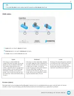
Page 77: ...by the user Rotational Following a contact established between the object grasped by the end effector or the effector itself and the corresponding mating part or surface a rotational motion is engaged...

Page 78: ...spiral move after the part tool has established contact with the mating part surface 7 Force initiating insertionparameter Textbox for the user to enter a force drop value indicating that the part to...

Page 79: ...ct the direction in which the tool will go to reach the destination 4 Advanced parametersbox Box that expands the advanced parameters menu when ticked 5 Linearspeed parameter Textbox for the user to e...

Page 80: ...ault value Reference frame Direction N A Tool Axis Direction N A Z Linear speed mm s 5 Force initiating rotation N 10 Rotation speed s 5 Maximum torque Nm 1 Maximum rotation angle Error condition 360...

Page 81: ...jects The default parameters of the function allow for a versatile demo or a quick test of the features while the advanced parameters make it a more customizable asset Howto add a Find Surface node l...

Page 82: ...the linear motion 7 Insert instructiontextbox Checkbox that inserts the corresponding stop condition in the robot program when ticked its main func tion is to facilitate the programming and improve t...

Page 83: ...the user shall record a Robotiq Path emulating the desired Move In a situation where the user wants to make contact with a surface in accordance with the user defined settings a Wait instruction can...

Page 84: ...ee options or torque feeding around an axis lower three options 2 Force Torque depending on which options were checked at step 1 the corresponding textboxes here should be filled with the desired forc...

Page 85: ...a situation where 10 N are applied exclusively along the Z axis with 20 stiffnessalong the X and Y axes and a deviation range that goes from 50 mm to 50 mm along all axes l The end effector will syst...

Page 86: ...le pulling back less and less over time Fig 4 29 End effector experiencing adaptive stiffness upon repeated contact with a surface on CB Series Current vstargeted position From the Force Control node...

Page 87: ...External Tool Finishing Kit Instruction Manual Fig 4 30 Force control for e Series Fig 4 31 Force control for CB Series 87...

Page 88: ...t that will be processed within the Force Control node l Use the current position option when your defined trajectory may not resemble to the actual part that is being processed Motion Frame From the...

Page 89: ...direction the Z axis is perpendicular to the X axis and is close to the robot s Zaxis Test The Test button applies the user defined settings of the Force Control node to the sensor therefore moving al...

Page 90: ...Finishing Copilot software package includes Force Event which can be used to perform a click detection or to wait for a specific force or torque Howto add a Force Event function l On the teach pendan...

Page 91: ...an operation to add to the Force Event sequence 1 Wait forForce function 2 Clickdetection function Wait forForce The Wait for force feature is used to detect a specific force or torque inside a Force...

Page 92: ...goes to the following instructions Indeed a program instruction can be added if no click is detected Tip To perform a click button action as shown by the animated gif a Find Surface function has to be...

Page 93: ...e defined limits By default the program does not monitor forces and torques Howto add a CollisionDetection l OnCB Series From the PolyScope home page tap Program Robot and create or load a robot progr...

Page 94: ...or CB Series robot Thus any forces or torques applied to the robot arm will not be detected Only those applied to the end of arm tooling are monitored The Collision Detection feature in the installati...

Page 95: ...se_force index function returns the current wrench force and torque vector value applied at the robot arm base l The express_force_in_frame T_from_to wrench_from function is used to convert the wrench...

Page 96: ...gure below represents the gripper dimensions with axes X Y Z and origin referenced for finger motion Info All technical drawings in the current section depict aluminum fingers Fig 5 1 General dimensio...

Page 97: ...xceed 100 N regardless of the direction Please refer to the Moment and force limits section for more details Warning The following limits must be respected at all times Calculation of maximum moment a...

Page 98: ...p holders To install fingertips on racks use fingertip holders HND TIP HLD KIT and refer to the Spare Parts Kitsand Accessoriessection of the Hand E Instruction Manual You may customize fingertips to...

Page 99: ...KIT please refer to the Spare Parts Kitsand Accessoriessection This fingertip has a grooved surface with an optimal shape for picking cylindrical parts by its horizontal and vertical grooves This fin...

Page 100: ...permanently damage the Force Torque Sensor Fx 300 Fy 300 Fz 300 Mx 30 My 30 Mz 30 500 Outside diameter 75 mm Thickness 37 5 mm Stiffness Fx Fy 35 X 106 N m Fz 30 X 106 N m Mx My 10 000 Nm rad Mz 20 00...

Page 101: ...lculate the recommended friction payload W where l Fis the force applied by the gripper to the load l Cf is the friction coefficient between fingertip and part load l Sf is a safety factor to be deter...

Page 102: ...standing still When accelerating the payload will decrease The biggest factor in such calculations will always be the frictioncoefficient we recommend testing the coefficient Warning You must conside...

Page 103: ...l The yellowcurve in the graph represents the maximum force payload F recommended at given Zoffset for a custom finger design mounted directlyonthe rackwiththree 3 M3 screws Info The data is calculat...

Page 104: ...pecific cases with regards to your own application the main item to address is the strength of the screws used for mounting the fingers Friction grasp and form fit grasp Fig 5 10 Hand E grasps Maximum...

Page 105: ...5 2 3 Center of massand tool center point of the FTSensor and the Hand EGripper Couplingsare included whenGrippersare not mounted onthe Camera 105...

Page 106: ...clude robot acceleration and safety factors Parameter Hand E withAluminum Fingers Fx Fy Fz 100 N Mx 2 65 Nm My 3 74 Nm Mz 2 00 Nm Moments in x and y are calculated from the base of the fingers as show...

Page 107: ...rical interface RS 485 Recommended fuse Phoenix 0916604 UT6 TMC M 1 A Recommended power supply TDK Lambda DPP Series 15W Single Output DIN Rail Mount Power Supply DPP15 24 5 4 Electrical specification...

Page 108: ...and E Gripper requires only external maintenance with limited downtime Please refer to the Maintenance section of the Hand E Instruction Manual available on www support robotiq com External Tool Finis...

Page 109: ...the robot side Spare parts kits and accessories list Item Description Ordering Number External Tool Finishing Kit for URCB Series 1 x Hand E Gripper and FT 300 Sensor Kit for UR HND FTS UR KIT ETF CB...

Page 110: ...8 Troubleshooting Please refer to the Troubleshooting section of the Hand E Instruction Manual available on www support robotiq com External Tool Finishing Kit Instruction Manual...

Page 111: ...9 Warranty Please refer to the Warranty section of the Hand E and the FT Sensor Instruction Manuals available on www support robotiq com External Tool Finishing Kit Instruction Manual...

Page 112: ...more details about the original EC declaration of incorporation the applied standards and the Ingress Protection Certificate of the Hand E Gripper please refer to this section in the Hand E Instructi...

Page 113: ...e at 500 966 chemin Olivier L vis Qu bec Canada G7A 2N1 which specializes into the conception advanced manufacturing and sale of robotic products the Licensor s Business End User means a customer auth...

Page 114: ...will be made available thereof Fees The End User shall pay the Licensor for using the software as per the Order Summary The fees shall cover upgrades and patches of the Software provided by the Licens...

Page 115: ...ination of this Agreement for any reason the End User shall promptly uninstall the Software on any UR s Products and Licensor s Products computer or server on which it has been installed deliver to th...

Page 116: ...greed that this Agreement and all related documents be drafted in English only Les parties aux pr sentes confirment qu elles ont accept que la pr sente convention et tous les documents y aff rents soi...

Page 117: ...side USand Canada Technical support and engineering option 3 Sales option 2 Head office Robotiq 966 chemin Olivier Suite 500 St Nicolas Qu bec G7A 2N1 Canada Where automation Pros come to share their...

Reviews: