background image

2/22/2018

ROBOTIS e-Manual

http://emanual.robotis.com/docs/en/dxl/x/xm430-w210/

9/34

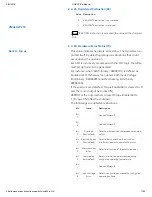
Value

Baud Rate Margin of Error

7

4.5M

0.000%

6

4M

0.000%

5

3M

0.000%

4

2M

0.000%

3

1M

0.000%

2

115,200

0.000%

1(Default)

57,600

0.000%

0

9,600

0.000%

 Note 

 Less than 3% of the baud rate error margin will not affect

to UART communication.

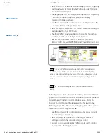
2. 4. 5. Return Delay Time(9)

After the DYNAMIXEL receives an Instruction Packet, it delays
transmitting the Status Packet for Return Delay Time (9). For
instance, if the Return Delay Time(9) is set to ‘10’, the Status
Packet will be returned after 20[μsec] when the Instruction
Packet is received.

Unit

Value

Range

Description

2[μsec]

0 ~ 254

Default value ‘250’(500[μsec]), Maximum

508[μsec]

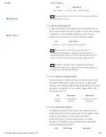
2. 4. 6. Drive Mode(10)

Drive Mode is availabe from the firmware version 38.

Bit

Item

Description

Bit 1(0x02) ~

7(0x80)

N/A

Unused, always ‘0’

Bit 0(0x01)

Direction of

Rotation

Normal Mode(0): CCW(Positive),

CW(Negative) 

Reverse Mode(1): CCW(Negative),

CW(Positive)

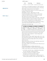
2. 4. 7. Operating Mode(11)

Value

Operating
Mode

Description

XM430-W210

Back to Top ▲

Summary of Contents for DYNAMIXEL XM430-W210

Page 1: ... Motor Coreless Motor Baud Rate 9600 bps 4 5 Mbps Control Algorithm PID control Degree of Precision 0 088 Operating Modes Current Control Mode Velocity Control Mode Position Control Mode 0 360 Extended Position Control Mode Current based Position Control Mode PWM Control Mode Voltage Control Mode Weight 82g Dimensions W x H x D 28 5mm x 46 5mm x 34mm Gear Ratio 212 6 1 Stall Torque 2 7N m 11 1V 2 ...

Page 2: ...t Realtime tick Trajectory Temperature Input Voltage etc Part Material Full Metal Gear Metal Front Middle Engineering Plastic Back 1 1 Performance Graph Note The max torque measurement method for the Stall Torque and Performance Graph is different Stall torque is measured from the max torque that it can reach This is generally how RC servos measure their torque For the Performance graph with the N...

Page 3: ...ddress is a unique value when accessing a specific Data in the Control Table with Instruction Packets In order to read or write data users must designate a specific Address in the Instruction Packet Please refer to Protocol 2 0 for more details about Instruction Packets Note Two s complement is applied for the negative value For more information please refer to Two s complement from Wikipedia 2 1 ...

Page 4: ...MIXEL is turned on Initial Values in the RAM area are restored when the DYNAMIXEL is turned on 2 2 Control Table of EEPROM Area Address Size Byte Data Name Description Access Initial Value 0 2 Model Number Model Number R 1030 2 4 Model Information Model Information R 6 1 Firmware Version Firmware Version R 7 1 ID DYNAMIXEL ID RW 1 8 1 Baud Rate Communication Speed RW 1 9 1 Return Delay Time Respon...

Page 5: ...it Minimum Position Limit RW 0 63 1 Shutdown Shutdown Error Information RW 52 2 3 Control Table of RAM Area Address Size Byte Data Name Description Access Initial Value 64 1 Torque Enable Motor Torque On Off RW 0 65 1 LED Status LED On Off RW 0 68 1 Status Return Level Select Types of Status Return RW 2 69 1 Registered Instruction Check Reception of Instruction R 0 70 1 Hardware Error Status Hardw...

Page 6: ...oal Position Target Position Value RW 120 2 Realtime Tick Count Time in millisecond R 122 1 Moving Movement Status R 0 123 1 Moving Status Detailed Information of Movement Status R 0 124 2 Present PWM Current PWM Value R 126 2 Present Current Current Current Value R 128 4 Present Velocity Current Velocity Value R 132 4 Present Position Current Position Value R 136 4 Velocity Trajectory Target Velo...

Page 7: ...ect Data 2 RW 0 226 1 Indirect Data 3 Indirect Data 3 RW 0 249 1 Indirect Data 26 Indirect Data 26 RW 0 250 1 Indirect Data 27 Indirect Data 27 RW 0 251 1 Indirect Data 28 Indirect Data 28 RW 0 578 2 Indirect Address 29 Indirect Address 29 RW 634 580 2 Indirect Address 30 Indirect Address 30 RW 635 582 2 Indirect Address 31 Indirect Address 31 RW 636 628 2 Indirect Address 54 Indirect Address 54 R...

Page 8: ...Torque Enable 64 is cleared to 0 2 4 1 Model Number 0 This address stores model number of the DYNAMIXEL 2 4 2 Firmware Version 6 This address stores firmware version of the DYNAMIXEL 2 4 3 ID 7 The ID is a unique value in the network to identify each DYNAMIXEL with an Instruction Packet 0 252 0xFC values can be used as an ID and 254 0xFE is occupied as a broadcast ID The Broadcast ID 254 0xFE can ...

Page 9: ...smitting the Status Packet for Return Delay Time 9 For instance if the Return Delay Time 9 is set to 10 the Status Packet will be returned after 20 μsec when the Instruction Packet is received Unit Value Range Description 2 μsec 0 254 Default value 250 500 μsec Maximum 508 μsec 2 4 6 Drive Mode 10 Drive Mode is availabe from the firmware version 38 Bit Item Description Bit 1 0x02 7 0x80 N A Unused...

Page 10: ...s position This mode is identical to the Multi Turn Mode from existing DYNAMIXELs 512 turns are supported 256 rev 256 rev This mode is ideal for multi turn wrists or conveyer systems or a system that requires an additional reduction gear 5 Current based Position Control Mode This mode controls both position and current torque Up to 512 turns are supported 256 rev 256 rev This mode is ideal for a s...

Page 11: ...rity than Secondary ID 12 i e if Secondary ID 12 and ID 7 are the same ID 7 will be applied first 3 The EEPROM area of the Control Table cannot be modified with Secondary ID 12 Only the RAM area can be modified 4 If Instruction Packet ID is the same as Secondary ID 12 the Status Packet will not be returned 5 If the value of Secondary ID 12 is 253 or higher the Secondary ID function is deactivated ...

Page 12: ...l for more details about the protocol 2 4 10 Homing Offset 20 Users can adjust the Home position by setting Home Offset 20 The Homing Offset value is added to the Present Position 132 Present Position 132 Actual Position Homing Offset 20 Unit Value Range Description about 0 088 1 044 479 1 044 479 255 255 rev 4 096 resolution Note In case of the Position Control Mode Joint Mode that rotates less t...

Page 13: ...ere damage 2 4 13 Min Max Voltage Limit 32 34 These values are maximum and minimum operating voltages When current input voltage acquired from Present Input Voltage 144 exceeds the range of Max Voltage Limit 32 and Min Voltage Limit 34 Voltage Range Error Bit 0x01 and Hardware Error Bit 0x80 in the Hardware Error Status 70 are set If Input Voltage Error Bit 0x10 is configured in the Shutdown 63 To...

Page 14: ...d in all operating mode except PWM Control Mode in order to generate a target trajectory For more details please refer to the Profile Velocity 112 Unit Value Range 214 577 Rev min2 0 32 767 Note Bit information of the Error field in the Status Packet is different from protocol 1 0 and protocol 2 0 This manual complies with protocol 2 0 Please refer to the Protocol section of e Manual for more deta...

Page 15: ...0 REBOOT is the only method to reset Torque Enable 64 to 1 Torque ON after the shutdown The followings are detectable situations Bit Item Description Bit 7 Unused Always 0 Bit 6 Unused Always 0 Bit 5 Overload Error default Detect persistent load that exceeds maximum output Bit 4 Electrical Shock Error default Detect electric shock on the circuit or insufficient power to operate the motor Bit 3 Mot...

Page 16: ... Position 132 2 4 21 LED 65 Turn on or turn off the LED on Dynamixel Bit Description 0 Default Turn OFF the LED 1 Turn ON the LED 2 4 22 Status Return Level 68 This value decides how to return Status Packet when Dynamixel receives an Instruction Packet Value Responding Instructions Description 0 PING Instruction Status Packet will not be returned for all Instructions 1 PING Instruction READ Instru...

Page 17: ... Voltage Error binary 00000001 and Overheating Error binary 00000100 If those errors are detected Torque Enable 64 is cleared to 0 and the motor output becomes 0 REBOOT is the only method to reset Torque Enable 64 to 1 Torque ON after the shutdown The followings are detectable situations Bit Item Description Bit 7 Unused Always 0 Bit 6 Unused Always 0 Bit 5 Overload Error default Detect persistent...

Page 18: ...tion Velocity I Gain 76 KVI KVI KVI TBL 65 536 0 16 383 I Gain Velocity P Gain 78 KVP KVP KVP TBL 128 0 16 383 P Gain Below figure is a block diagram describing the velocity controller in Velocity Control Mode When the instruction transmitted from the user is received by DYNAMIXEL it takes following steps until driving the horn 1 An Instruction from the user is transmitted via DYNAMIXEL bus then r...

Page 19: ...internal controller is abbreviated to KPP and that of the Control Table is abbreviated to KPP TBL Controller Gain Conversion Equations Range Description Position D Gain 80 KPD KPD KPD TBL 16 0 16 383 D Gain Position I Gain 82 KPI KPI KPI TBL 65 536 0 16 383 I Gain Position P Gain 84 KPP KPP KPP TBL 128 0 16 383 P Gain Feedforward 2nd Gain 88 KFF2nd KFF2nd TBL 4 0 16 383 Feedforward Acceleration Ga...

Page 20: ...ent 126 Note In case of PWM Control Mode both PID controller and Feedforward controller are deactivated while Goal PWM 100 value is directly controlling the motor through an Inverter In this manner users can directly control the supplying voltage to the motor Note Ka is an Anti windup Gain that cannot be modified by users Below figure is a block diagram describing the current based position contro...

Page 21: ...tween the controller and DYNAMIXEL communication RS485 TTL is disconnected due to an unspecified error Communication is defined as all the Instruction Packet in the DYNAMIXEL Protocol Values Description Unit 20 ms Range 0 Deactivate Bus Watchdog Function Clear Bus Watchdog Error Range 1 127 Activate Bus Watchdog Range 1 Bus Watchdog Error Status The Bus Watchdog function monitors the communication...

Page 22: ...ccess to the Goal Value will be changed to read only 6 If 150 is written to the Goal Velocity 104 Range Error will be returned via Status Packet 7 If the value of Bus Watchdog 98 is changed to 0 Bus Watchdog Error will be cleared 8 If 150 is written in the Goal Velocity 104 the DYNAMIXEL will rotate in CCW direction 2 4 28 Goal PWM 100 In case of PWM Control Mode both PID controller and Feedforwar...

Page 23: ...y voltage 12 V Note If Profile Acceleration 108 and Goal Velocity 104 are modified simultaneously modified Profile Acceleration 108 will be used to process Goal Velocity 104 2 4 31 Profile Acceleration 108 The acceleration of Profile can be set with this value Profile Acceleration 108 can be used in all control modes except Torque Control Mode Profile Acceleration 108 cannot exceed Acceleration Li...

Page 24: ...e Acceleration 108 is abbreviated to APRFL X stands for Don t Care case When given Goal Position 116 Dynamixel s profile creates target velocity trajectory based on current velocity initial velocity of the Profile When Dynamixel receives updated target position from a new Goal Position 116 while it is moving toward the previous Goal Position 116 velocity smoothly varies for the new target velocity...

Page 25: ...reach Goal Position 116 is calculated as below Condition Types of Profile VPRFL 112 0 Profile not used Step Instruction VPRFL 112 0 APRF 108 0 Rectangular Profile VPRFL 112 0 APRF 108 0 VPRFL_TRI VPRFL 112 Triangular Profile VPRFL 112 0 APRF 108 0 VPRFL_TRI VPRFL 112 Trapezoidal Profile Note Dynamixel supports Jerk control in order to minimize dramatic change of acceleration Therefore actual trave...

Page 26: ...Description Position Control Mode Min Position Limit 52 Max Position Limit 48 Initial Value 0 4 095 Extended Position Control Mode 1 048 575 1 048 575 256 rev 256 rev Current based Position Control Mode 1 048 575 1 048 575 256 rev 256 rev Degree Conversion Constant Description 0 088 Value 1 rev 0 4 095 Note If Profile Acceleration 108 Profile Velocity 112 and Goal Position 116 are modified simulta...

Page 27: ...ion about the movement Following Error Bit 0x08 and In Position Bit 0x01 only work with Position Control Mode Extended Position Control Mode Current based Position Control Mode Details Description Bit 7 0x80 Unused Bit 6 0x40 Unused Bit 5 Bit 4 0x30 Profile Type 0x30 Profile Type 0x20 Profile Type 0x10 Profile Type 0x00 Trapezoidal Velocity Profile Triangular Velocity Profile Rectangular Velocity ...

Page 28: ... within 1 rev 0 4 095 when Torque is turned on in Position Control Mode Reset Present Position 132 value can be affected by Homing Offset 20 2 4 41 Velocity Trajectory 136 This is a target velocity trajectory created by Profile Operating method can be changed based on control mode For more details please refer to the Profile Velocity 112 1 Velocity Control Mode When Profile reaches to the endpoint...

Page 29: ...ead Only Read Write For instance allocating 65 Address of LED to Indirect Address 1 168 Indirect Data 1 224 can perform exactly same as LED 65 Example 1 Allocating Size 1 byte LED 65 to Indirect Data 1 224 1 Indirect Address 1 168 change the value to 65 which is the address of LED 2 Set Indirect Data 1 224 to 1 LED 65 also becomes 1 and LED is turned on 3 Set Indirect Data 1 224 to 0 LED 65 also b...

Page 30: ...signed to Indirect Address Note In order to allocate Data in the Control Table longer than 2 byte to Indirect Address all address must be allocated to Indirect Address like the above Example 2 Note Indirect Address 29 56 and Indirect Data 29 56 can only be accessed with Protocol 2 0 3 How to Assemble 3 1 Wiring through Back Case XM430 W210 Back to Top ...

Page 31: ...e assembly through hollow case Organize the entangled cable before assembling the back case Do not assemble the back case with entangled cable The entangled cable can be squashed by the case and cause communication error 3 2 Option Frame Assembly 4 Maintenance 4 1 Horn and Bearing Replacement XM430 W210 Back to Top ...

Page 32: ... align the horn to the wheel gear serration by aligning dots Once alignment is properly done gently push the center of the horn toward the actuator Make sure that the horn washer is in place as you tighten the bolt 4 1 2 Installing the Bearing Set You may need to remove the bearing set from the previous actuator and reinstall it into the new actuator The bearing set can also be purchased separatel...

Page 33: ...icro USB cable 5 1 0 2 R Manager 2 0 Install In order to change settings of DYNAMIXEL R Manager 2 0 must be installed on your system You can also use Dynamixel SDK or Dynamixel Workbench 5 2 Connector Information Item TTL RS 485 Pinout 1 GND 2 VDD 3 DATA 1 GND 2 VDD 3 DATA 4 DATA Diagram Housing JST EHR 03 JST EHR 04 PCB Header JST B3B EH A JST B4B EH A Crimp Terminal JST SHE 001T P0 6 JST SHE 001...

Page 34: ...2 22 2018 ROBOTIS e Manual http emanual robotis com docs en dxl x xm430 w210 34 34 Download X_430_std_ref pdf 2018 ROBOTIS Powered by Jekyll Minimal Mistakes XM430 W210 Back to Top ...

Reviews: