RT-7690-2 User Guide
19
Calibration
The RT-7690-2 laser system is calibrated before shipment to ensure that you receive a superior
product conforming to the product specifications listed. Although it has been calibrated before
leaving the factory, it contains many precision-machined parts that may be affected if the
instrument is subject to abuse. Therefore, if the unit is ever dropped or sustains significant impact,
the user should check calibration. We also recommend that you calibrate your tool periodically as
a normal maintenance procedure.
To calibrate the RT-7690-2 laser system:
1. Select a site to be used as a calibration range that will allow the base unit to be placed about
50 ft. (15m) away from a smooth vertical surface such as a wall. Use a flathead screwdriver
to remove the calibration port covers on the side and front of the unit. Store the calibration
port covers in a safe place.
2. Set the unit on a level surface at one end of the range. Position it with the side facing the wall.
The calibration port should be facing away from the wall.
3. Turn on the power and the level laser beam. Select Dither/Scan mode (at the shortest line
length) for best laser beam visibility. If the beam is not visible, use the laser detector to locate
the beam.
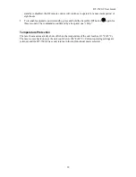
4. Mark the height of the laser beam (center of the laser beam) on the vertical surface of the wall
as A.
50 ft. (15m)
A
*
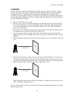
5. Rotate the unit 180 degrees, taking care not to change the height of the device. The laser unit
should be positioned with the other side of the unit facing the same vertical wall as in step 2.
Use the level Line Dither/Scan position arrows to position the laser beam on the original wall.
6. Mark the height of the laser beam on the same vertical surface as B.
50 ft. (15m)
Y
B
*
If this second marking is positioned at the same height as the mark made in step 4, proceed to
step 11. Otherwise, continue to step 7.
The goal of the next few steps is to position the level beam at a height halfway between the marks
made in steps 4 and 6.


