background image


RT-7690-2 User Guide 

23 


Limited Warranty 


Toolz warrants for a period of one (1) calendar year from the date of purchase that its 
products are free of defect in material and workmanship, and conform to Toolz’s published 
technical specifications under normal operating conditions. 
 
This Warranty


is void and does not apply if the product has been damaged by accident, abuse, 

misuse, normal wear and tear, or if the product has been modified, altered, or the case 
opened, or is repaired by anyone other than Toolz or its authorized repair center(s).  
 
Toolz will, at its option and expense, repair or replace any products found to be defective 
under the above warranty.  Repairs and replacement units may contain new and/or 
reconditioned components. 
 

EXCEPT AS EXPRESSLY SET FORTH ABOVE, 

TOOLZ MAKES NO 

WARRANTIES, EXPRESS OR IMPLIED, INCLUDING BUT NOT LIMITED TO ANY 
IMPLIED WARRANTIES OF MERCHANTABILITY OR FITNESS FOR A 
PARTICULAR PURPOSE, AND TOOLZ EXPRESSLY DISCLAIMS ALL WARRANTIES 
NOT LISTED ABOVE.  Some jurisdictions do not allow limitations on how long an implied 
warranty lasts, so the above limitation may not apply to you.  This warranty gives you 
specific legal rights, and you may also have other rights, which vary by jurisdiction. 
 
TOOLZ SHALL IN NO EVENT BE LIABLE FOR ANY LOST PROFITS, LOST 
BUSINESS, COST OF REPLACEMENT GOODS, OR ANY CONSEQUENTIAL, 
INCIDENTIAL, INDIRECT, SPECIAL OR PUNITIVE DAMAGES, ARISING OUT OF 
OR RELATING IN ANY WAY TO THE PRODUCT OR USE OF OR INABILITY TO 
USE THE PRODUCT, WHETHER OR NOT BASED ON CONTRACT, TORT 
(INCLUDING NEGLIGENCE AND STRICT LIABILITY) OR OTHERWISE.   TOOLZ’S 
MAXIMUM LIABILITY UNDER THIS WARRANTY SHALL NOT EXCEED THE 
PRICE PAID FOR THE GOODS UPON WHICH SUCH LIABILITY IS BASED.  The 
foregoing limitations will apply even if any warranty or remedy provided under this 
Agreement fails of its essential purpose.  Some jurisdictions do not allow the exclusion or 
limitation of incidental or consequential damages, so the above limitation or exclusion may 
not apply to you. 


Summary of Contents for RT-7690-2

Page 1: ...emote controlled simultaneous level and plumb rotational laser system User Guide Toolz 404 Villa Street Mountain View CA 94041 800 984 0404 Domestic Revision 1 650 903 4944 International July 2002 www robotoolz com 080 0020 01 ...

Page 2: ...n the Laser System 6 Using the Lasers 6 Operating Modes 7 Out of Level 8 Laser Detector 8 Using the Reflective Target 11 Using the Laser Enhancement Glasses 11 Applications 12 Level 12 Plumb 13 Align 14 Grade 15 Power 16 Base Unit 16 RF Remote Laser Detector 17 Temperature Protection 18 Calibration 19 Care and Maintenance 22 Warranty Information 23 Specifications 24 ...

Page 3: ...e FCC rules These limits are designed to provide reasonable protection against harmful interference in a residential installation This equipment generates uses and can radiate radio frequency energy and if not installed and used in accordance with the instructions may cause harmful interference to radio communications However there is no guarantee that interference will not occur in a particular i...

Page 4: ...in 3 mm at 100 ft 30m Plumb 1 4 in 6 4 mm at 100 ft 30m Level and plumb Spin mode Variable rotation speeds 350 600 and 1200 rpm Plumb alignment 2 0 degrees Level and plumb Line Dither Scan mode for higher beam visibility Six line lengths 360 level and plumb positioning End user calibration Pendulum lock mechanism for protection during transport and storage Out of level indicator Automatic power st...

Page 5: ...ase Unit front Retractable Antenna Tripod Mount Level Laser Aperture Helmet Plumb Laser Aperture Helmet Plumb Laser Aperture Level Laser Aperture Handle Battery Compartment Base Unit back Power Switch Pendulum Lock Laser Controls Base Unit LED AC DC Port Retractable Antenna Laser Controls LCD Display Detector Panel RF Remote Control Laser Detector X Y X Y Calibration Port CA ...

Page 6: ... control laser detector Refer to the following illustrations for the location of the operating controls RT 7690 2 Base Unit Controls Level Laser Controls Plumb Laser Controls Level Laser On Off Level Clockwise Counterclockwise Position Line Dither Scan Plumb Clockwise Counterclockwise Position Line Dither Scan Level Line Dither Scan Mode Plumb Alignment Plumb Line Dither Scan Mode Level Spin Mode ...

Page 7: ...b Clockwise Counterclockwise Line Dither Scan Position Level Line Dither Scan Mode Plumb Alignment Plumb Line Dither Scan Mode Level Spin Mode Speed Select Plumb Spin Mode Speed Select Detector Coarse Fine Select Detector Beeper On Off Detector Panel RF Remote Detector Power On Off Plumb Laser On Off RF Remote Detector Power On Off X Y X Y Note The LCD display icons are described in the Laser Dete...

Page 8: ...has turned to a steady green 3 Turn on the level or plumb laser from the base unit or RF remote control Caution Both lasers and the main power switch should always be turned off before transporting or storing the base unit Using the Lasers The RT 7690 2 laser system s level and plumb lasers operate independently You can turn on the level laser the plumb laser or both lasers simultaneously Use the ...

Page 9: ...or applications A plumb alignment is available for the plumb laser in Spin mode with a range of 2 0 around the center of rotation The default position is the midpoint of the 4 adjustment range The base unit emits a constant beep is emitted if the adjustment limit is reached Note To enter Spin mode from Line Dither Scan mode press the level or plumb Spin button on the keypad Line Dither Scan mode W...

Page 10: ...base unit resumes the mode of the last signal sent to the base unit Note The out of level indicator overrides all other indicators If the laser system is in low battery mode or in standby mode and the laser system becomes out of level the out of level indicator will override the low battery indicator or standby mode indicator Laser Detector The detector allows accurate detection of the laser beam ...

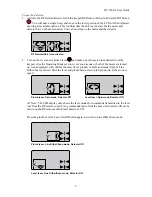
Page 11: ...ating Modes section As soon as one or both of the lasers are turned on icons displayed will confirm the laser level plumb or both and mode Spin or Line Dither Scan selected Both the level and plumb lasers start up in Spin mode at the slowest speed Y X Plumb laser Spin mode Detector Off Level laser Spin mode Detector Off Note The LCD display only shows the laser modes for commands transmitted to th...

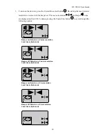
Page 12: ... and beeper icons are displayed on the LCD Continue pressing the Coarse Fine button to cycle through the following options X Beeper on Detector on Coarse resolution Level Laser Spin mode X Beeper off Detector on Coarse resolution Level Laser Spin mode X Beeper on Detector on Fine resolution Level Laser Spin mode X Beeper off Detector on Fine resolution Level Laser Spin mode X ...

Page 13: ...d with the center of the detector sensor panel both arrows on the LCD display are lit and the beep is continuous indicating that it is properly centered Note Detector orientation depends on whether the detector is being used to locate the level or plumb laser beam Level laser detection Plumb laser detection 6 To turn off the RF remote control laser detector press the power on off button There is a...

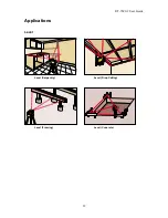
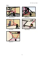
Page 14: ...RT 7690 2 User Guide 12 Applications Level Level Carpentry Level Drop Ceiling Level Framing Level Concrete ...

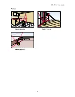
Page 15: ...RT 7690 2 User Guide 13 Plumb Plumb Carpentry Plumb Framing Plumb Concrete ...

Page 16: ...RT 7690 2 User Guide 14 Align Align Carpentry Align Framing Align Tiling Align Flooring Align HVAC ...

Page 17: ...RT 7690 2 User Guide 15 Grade Grade Concrete ...

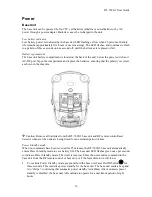
Page 18: ...n in the diagram Caution Remove all batteries from the RT 7690 2 base unit and RF remote control laser detector whenever the units are being stored for an extended period of time Power Standby mode When no commands have been received for 25 minutes the RT 7690 2 base unit automatically enters Power Standby mode to save battery life The base unit LED flashes green once per second to indicate Power ...

Page 19: ...ol detector battery compartment is located at the back of the unit Open the compartment and replace the 9V battery ensuring that the polarity is correct as shown in the diagram Caution Remove all batteries from the RT 7690 2 base unit and RF remote control laser detector whenever the units are being stored for an extended period of time Power Standby mode The RF remote control laser detector enter...

Page 20: ...e Laser On Off button again for three seconds The command is confirmed by a beep and one chirp Temperature Protection The laser beam automatically shuts off when the temperature of the unit reaches 113 F 45 C The laser comes back on once the unit cools below 104 F 40 C Current operating settings are retained and the RT 7690 2 base unit returns to the last functional mode selected ...

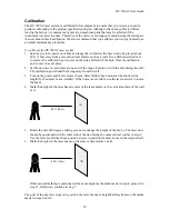
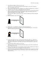
Page 21: ...e 2 Set the unit on a level surface at one end of the range Position it with the side facing the wall The calibration port should be facing away from the wall 3 Turn on the power and the level laser beam Select Dither Scan mode at the shortest line length for best laser beam visibility If the beam is not visible use the laser detector to locate the beam 4 Mark the height of the laser beam center o...

Page 22: ... C then proceed to step 12 12 Rotate the laser unit 90 degrees and position the it with the front facing the vertical surface Mark the height of the laser beam as D 50 ft 15m D C 13 Compare the height of D with C If the height of D matches the height of C calibration is complete Turn the power switch to the off position Screw back the calibration port covers and resume normal operation If the heig...

Page 23: ...turning the power on Calibration is complete 17 Turn the power switch to the off position Screw back the calibration port covers and resume normal operation Note Complete calibration of the level laser beam automatically calibrates the plumb laser beam Separate calibration of the plumb laser beam is not required ...

Page 24: ...ll enter the device Do not store it in hot areas above 158 F or 70 C High temperatures can shorten the life of electronic devices damage batteries and warp or melt certain plastics Do not store it in cold areas below 14 F or 10 C When the device warms up to its normal operating temperature moisture can form inside the base unit and or RF remote control laser detector where it may damage the circui...

Page 25: ...S FOR A PARTICULAR PURPOSE AND TOOLZ EXPRESSLY DISCLAIMS ALL WARRANTIES NOT LISTED ABOVE Some jurisdictions do not allow limitations on how long an implied warranty lasts so the above limitation may not apply to you This warranty gives you specific legal rights and you may also have other rights which vary by jurisdiction TOOLZ SHALL IN NO EVENT BE LIABLE FOR ANY LOST PROFITS LOST BUSINESS COST OF...

Page 26: ...ttery indicator Base unit Yellow LED flashes on for three seconds off for one second Five hours of use remaining RF remote control laser detector LCD display icon Out of level indicator Flashing red LED in sync with laser and beeper once per second Base unit Power Standby mode Activated after 25 minutes of no activity Indicated by rapidly flashing green LED RF remote control laser detector standby...

Reviews: