55
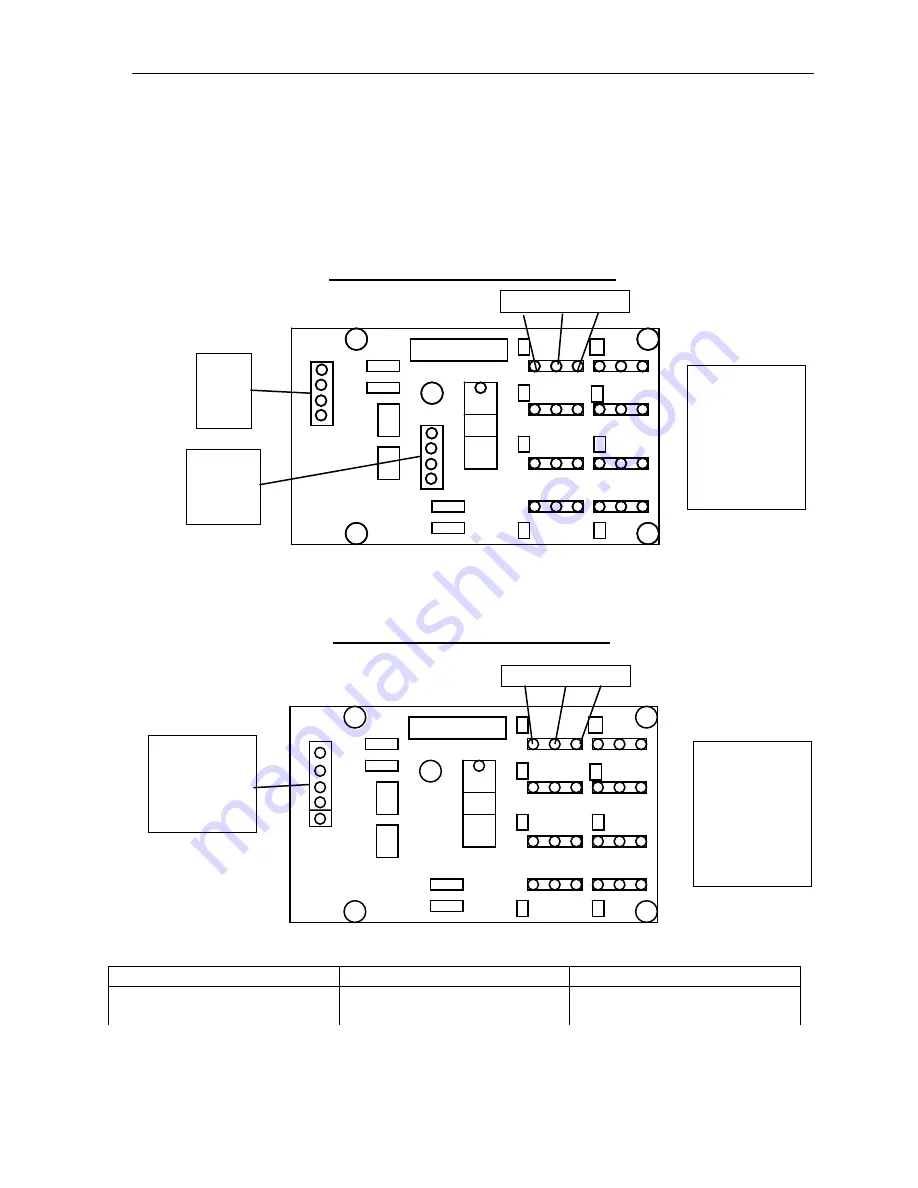
Appendix B: Eyes Servo Board - Patches
Eyes Servo Board
(Opto-Shift Register Board)
Version With Two 4 Pin Connections
White Black Red
4 Pin Connectors
Gray
Black
Yellow
NC
Red +5V
NC
NC
Black
1 Left Eyelid
2 Right Eyelid
3 Left Hand
4 Right Hand
5 Eyes L/R
6 Left Eyelid
7 Right Eyelid
8 Eyes L/R
Version With One 5 Pin Connection
White Black Red
Red + 5 V
Black
Gray
Yellow
Black (Brown)
5 Pin Connector
1 Left Eyelid
2 Right Eyelid
3 Left Hand
4 Right Hand
5 Eyes L/R
6 Left Eyelid
7 Right Eyelid
8 Eyes L/R
Robot
Typical Connection
Location of Board in Robot
Patches Robot
6,7, and 8
In Patches
1
2
3
4
5
6
7
8
COPYRIGHT 1993
ROBOTRONICS
4015
1
2
COPYRIGHT 1993
ROBOTRONICS
3
4
4015
5
6
7
8
1
2
COPYRIGHT 1993
ROBOTRONICS
3
4
4015
5
6
7
8
Summary of Contents for Patches & Pumper
Page 1: ...i Patches Pumper Robot Operating Manual Version 6C ...
Page 27: ...23 Chapter 4 Cassette Tape Player System Diagram Cassette Tape Player ...
Page 28: ...24 Chapter 4 Cassette Tape Player System Diagram ...
Page 47: ...43 APPENDIX A ...
Page 51: ...47 Appendix A Robot Functional Block Diagram Robot Functional Block Diagram ...
Page 52: ...48 APPENDIX B ROBOT PARTS IDENTIFICATION ...
Page 62: ...58 Notes ...
Page 63: ...59 Technical Tips ...


