background image

A-5 

ROBOVENT • DFS SERIES OWNER’S MANUAL

APPENDIX A

ePad Operator Instructions 

 (continued)

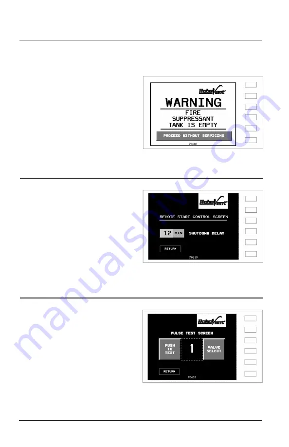
ALARM SCREEN 

 (continued)

ALARM SCREEN - 

(Optional Equipment)

Indicates the Fire Suppressant Tank is 
low or empty.
Unit will operate without tank being full 
but it is not advised.
When 

Proceed Without Servicing


button is pressed, screen is switched to 
Screen #2

REMOTE START CONTROL -  

(Optional Equipment)

Amount of time (in minutes) equipment 
continues to run after the remote start 
signal ends.
Value usually set between 5 - 15.
Touch display box to bring up number 
entry screen.

SCREEN 10

PULSE TEST

Push to Test energizes the value that is 
shown.
Valve Select cycles through the values.
This screen can be helpful with 
diagnostics. The number displayed, 
shows the next valve to be energized 
while running.

SCREEN 8

Summary of Contents for FloorSaver Series

Page 1: ...Owner s Manual Installation Operation Maintenance Revised 11 30 20 FloorSaver Series DFS Dust Collectors ...

Page 2: ......

Page 3: ...DFS 4000 4 DFS 6000 6 DFS 8000 8 DFS 12000 12 Owner s Manual Installation Operation Maintenance Manufactured by RoboVent 37900 Mound Road Sterling Heights MI 48310 USA 888 762 6836 www robovent com 2016 RoboVent All rights reserved ...

Page 4: ...eds scheduled maintenance keep in mind that your local RoboVent distributor has technicians specially trained in servicing our collectors We would be pleased to set up a preventative maintenance program or answer your questions and concerns At RoboVent we are committed to making your plant a safe and healthy environment for your workers Please take time to read this manual thoroughly before instal...

Page 5: ...nstallation Section 600 Pages 17 18 Operation Section 700 Pages 19 20 Standard Maintenance Procedure Section 800 Pages 21 22 Filter Change Maintenance Procedure Section 800 Pages 23 25 VFD Maintenance Procedure Section 900 Pages 26 27 Motor Greasing Guide Section 1000 Pages 28 37 Troubleshooting Section 1100 Pages 38 39 Appendix A ePad Electronic Programmable Controller Instruction Manual Appendix...

Page 6: ...nd electrical components Any blockage of the air flow will decrease efficiency of this unit 4 Refer all service matters to qualified service personnel Servicing is required when the unit is damaged in any way including the control panel supply wiring or in the case of excessive filter loading 5 Risk of serious personal injury or death Use extreme care to make sure you are never in a position where...

Page 7: ...eases filter life by 30 to 40 over traditional horizontal filter placement 3 High Performance Blower Design Each DFS Series Dust Collector comes with Air Foil blowers with direct drive motors This highly efficient blower design and direct drive system maximizes the airflow CFM delivered by the motor power requirements see Figure 2 4 Filter Self Cleaning System FSS The DFS FloorSaver Series comes e...

Page 8: ...panel The ePad Controller can be accessed from the front panel allowing ease in changing the ePad Controller settings see Figure 5 8 Sturdy 10 GA Reinforced Collector Housing Construction This heavy duty construction secures a lifetime of industrial use Seams are robotic welded and ground to assure there are no leaks or cracks that could contaminate the facility air system Each unit is pre tested ...

Page 9: ...decreases ambient noise into the facility see Figure 8 12 Smoke Detection Shut Down System Each DFS unit is equipped with a Smoke Detection Shut Down System In the event that a fire or excessive smoke should appear in the clean air plenum the blower wheel and ePad Controller will automatically shut down and a strobe light will be activated 13 High Efficiency Pre Coated Filters High efficiency filt...

Page 10: ... specific arrangements are made otherwise Compare the number of items received against the carrier s bill of lading Inspect all items for apparent damage Immediately report any shortages or obvious damage to the carrier and to your local RoboVent Representative or call the factory at 1 888 762 6836 When all skids are completely unpacked and uncrated check all items received against the packing lis...

Page 11: ...cally the dislodged dust eventually works its way down to the lower collection tray This process reconditions the filter media and can prolong cartridge life for several months filter life depends upon your application General Operation Dust and smoke laden air is drawn through the floor of an enlarged intake plenum where it passes through a dual layered spark arrestor before entering the cartridg...

Page 12: ...s up to 50 E Pad XE Premium Controls Upgrade Model DFS 2000 2 Filter Media Comparable to 710 square feet Filter Cartridges 2 EX 14D36 A13 Blended Non Woven Media Nanofiber Electrical Requirements 480 Volt 3 phase 3 0 amps 3 7 amps Built in Spark Arrestance 2 Metal Mesh Part MM 17402 2 Spark Arrestance Baffles Part FB 17402 Pulse Valves 2 1 Electronically Actuated Solenoids Compressed Air Requireme...

Page 13: ...5 square feet Filter Cartridges 3 EX 14D36 A13 Blended Non Woven Media Nanofiber Electrical Requirements 480 Volt 3 phase 3 7 amps 6 2 amps and 9 2 amps Built in Spark Arrestence 2 Metal Mesh Part MM 17402 2 Spark Arrestence Baffles Part FB 17402 Pulse Valves 3 1 Electronically Actuated Solenoids Compressed Air Requirements 1 0 SCFM On Line Pulse 6 0 SCFM Off Line Pulse 80 PSI Silencing Built in A...

Page 14: ... square feet Filter Cartridges 4 EX 14D36 A13 Blended Non Woven Media Nanofiber Electrical Requirements 480 Volt 3 phase 6 2 amps 9 2 amps 17 5 amps Built in Spark Arrestance 2 Metal Mesh Part MM 17402 2 Spark Arrestance Baffles Part FB 17402 Pulse Valves 2 1 5 Electronically Actuated Solenoids Compressed Air Requirements 1 3 SCFM On Line Pulse 7 8 SCFM Off Line Pulse 80 PSI Silencing Built in Aco...

Page 15: ...square feet Filter Cartridges 6 EX 14D36 A13 Blended Non Woven Media Nanofiber Electrical Requirements 480 Volt 3 phase 9 2 amps 9 2 amps 23 5 amps Built in Spark Arrestance 3 Metal Mesh Part MM 17402 3 Spark Arrestance Baffles Part FB 17402 Pulse Valves 2 1 5 Electronically Actuated Solenoids Compressed Air Requirements 2 0 SCFM On Line Pulse 12 0 SCFM Off Line Pulse 80 PSI Silencing Built in Aco...

Page 16: ...ia Comparable to 2 840 square feet Filter Cartridges 8 EX 14D36 A13 Blended Non Woven Media Nanofiber Electrical Requirements 480 Volt 3 phase 9 2 amps 17 5 amps 23 5 amps Built in Spark Arrestance 4 Metal Mesh Part MM 17402 4 Spark Arrestance Baffles Part FB 17402 Pulse Valves 2 2 Electronically Actuated Solenoids Compressed Air Requirements 6 5 SCFM On Line Pulse 39 0 SCFM Off Line Pulse 80 PSI ...

Page 17: ...er Cartridges 12 EX 14D36 A13 Blended Non Woven Media Nanofiber Electrical Requirements 480 Volt 3 phase 17 5 amps 17 5 amps 23 5 amps 36 0 amps Built in Spark Arrestance 6 Metal Mesh Part MM 17402 6 Spark Arrestance Baffles Part FB 17402 Pulse Valves 2 1 5 Electronically Actuated Solenoids Compressed Air Requirements 2 6 SCFM On Line Pulse 15 6 SCFM Off Line Pulse 80 PSI Silencing Built in Acoust...

Page 18: ... or UL certification contact the RoboVent Service Department at 800 470 3430 A 460 volt 3 phase service should be connected to the provided lugs inside the J box as shown in Figure 11 Compressed Air Hook Up IMPORTANT First and foremost your DFS unit needs a clean dry compressed air source approximately 90 PSI Many problems can be traced back to the presence of either oil or water in the compressed...

Page 19: ...o be wired into the system Auto On Off Option For the Automatic Operation Option the supplied current transformer must be positioned around one of the power conductors to the welding power supply and secured so as to avoid physical damage This usually involves disconnecting the conductor installing the current transformer and then re connecting the system Fire Suppression System Your DFS equipment...

Page 20: ...ler With the Service Disconnect in the ON position press the SYSTEM START button on the touch screen this may either be remote or mounted on the unit to energize the control system then continue through the MAN FAN and LIGHTS and or START MODE screens if these option are applicable to the BLOWER CONTROL to engage the Motor Starters and start the system blowers Auto On Off Option If your system is ...

Page 21: ...mpressed air will back flush that line of cartridges This helps keep the dust loose so that the off line cleaning can remove the dust from the filter Off line cleaning happens automatically every time the system is shut down This is the most effective means of removing the dust from the filters The duration and frequency of this cleaning cycle is programmed into the controller see APPENDIX A IMPOR...

Page 22: ... to Automatic to stop the pulsing DO NOT start the motor 5 Remove and replace Spark Arrestance filters Metallic Baffle and metal mesh filter at the welding area inlets A Clean the entire inlet plenum to include i Spark deflector plate ii Spark arrestor filter metallic filter tracks and cover door iii Inlet Plenum Box inside and outside Note Most particulate can usually be vacuumed out however if i...

Page 23: ...ace 9 Turn on the collector and record the new P Static Pressure 10 Open the petcock valve on the solenoid accumulator and verify that there is no moisture in the compressed air stream 11 Check for excessive motor blower vibration 12 Check overall system for any loose bolts or screws and also door latches hinge wear 13 Verify that compressed air pressure is set to 80 PSI 14 Wipe off any major hand...

Page 24: ... void of pockets of particulate 7 Empty the dust tray and replace in its slot 8 Remove the Endurex paper pleated filters As a stack of filters are removed place the Top Pan located on the top of each stack over the filter seat at the bottom of the lower filter This is to prevent particulate from getting into the clean air side of the collector Continue until all filters are removed Close the filte...

Page 25: ...nism will turn right to left and make contact with the indentation on the center of the top pan Sometimes a slight movement of the filter stack is necessary to center the T handle top pan When T handle top pan contact is made continue turning roughly 14 18 1 2 turns until the filter stack is properly installed To verify proper installation place your hand on the seam of the 2 filters in the middle...

Page 26: ...ssure is set to 80 PSI 20 Wipe off any major hand prints off collector door control panel that may have gotten there while doing the service 21 Clean up any fallen debris from the system service Notes There are certain procedures that apply to both Quarterly as well as Major Maintenance If the Quarterly Maintenance was performed the previous month then those procedures can be skipped until the nex...

Page 27: ...sure the AC input output and DC Bus potential to insure safe levels prior to resuming work Failure to adhere to this warning may result in personal injury or death Clean off any dirt and dust with an air gun using clean and dry air at a pressure between 55 85 psi Replace the boards if they cannot be made clean Clean off any dirt and dust with an air gun using clean and dry air at a pressure betwee...

Page 28: ...y values Key functionality Clean X X X X X X X X X X X X X X X X X X X X X X X X X X X X X X X Environment Equipment AC Power Supply Conductors Wire Connections Transformers Reactors Terminal Blocks DC Bus Capacitors Relays Contactors Soft Charge Resistors Operation Cooling Fans Fins Heatsink Digital Operator General AC Power Circuit Devices Control Circuits Cooling System Keypad Display INSPECTIO...

Page 29: ...ROBOVENT FUSION 4 5 SERIES OWNER S MANUAL 65 SECTION 1000 Motor Greasing Guide ...

Page 30: ... can occur between rotating elements Follow RoboVent s Motor Greasing Guidelines to properly lubricate your electric motor NOTE 1Pump 1gramofgrease OUNCES OZ GRAMS G GREASE GUN PUMPS 0 1 oz 2 835 g 2 8 pumps 1 oz 28 35 g 28 pumps 2 oz 56 70 g 56 pumps 3 oz 85 05 g 84 pumps 4 oz 113 40 g 112 pumps 5 oz 141 75 g 140 pumps Grease Conversion Chart for use with this grease gun Manual Grease Gun Heavy D...

Page 31: ...tain T frame models will utilize special grease and will be noted on the lubrication nameplate Relubrication Time Interval Amounts Fill new grease until it overflows and the old grease is entirely replaced BEARING SIZE MOTOR HP GREASE 1800 RPM 3600 RPM AMOUNT HOUR CHANGE HOUR CHANGE IN GRAMS INTERVAL INTERVAL All motors listed are ODP DE NDE 6306ZZ 5 30 grams 3000 hours 2000 hours DE NDE 6306ZZ 7 ...

Page 32: ... 6 Wipe off excess grease and replace filler and drain plugs 7 Motor is ready for operation Approved Greases Chevron SRI 2 Rykon Premium 2 Exxon Polyrex EM Texaco Polystar RB Service Types Seasonal Service The motor remains idle for a period of 6 months or more Standard Service Up to 16 hours of operation per day indoors 100 F max ambient temp Severe Service Greater than 16 hours of operation per ...

Page 33: ...42 5 grams Relubrication Amounts 1800 RPM OVER 1800 RPM 1800 RPM OVER 1800 RPM 1800 RPM OVER 1800 RPM OR LESS OR LESS OR LESS SERVICE CONDITIONS Standard 3 yrs 6 months 2 yrs 6 months 1 year 3 months Severe 1 yr 3 months 1 yr 3 months 6 months 1 month Seasonal The motor remains idle for a period of 6 months or more Relubrication Time Interval NEMA FRAME SIZE IN RPMs 140 180 210 360 400 510 SECTION...

Page 34: ... motor for 1 minute at full speed 3 Then turn off the motor and pump in the rest of the grease Note The injection of all the grease with the motor in standstill can make the grease penetrate into the motor through the bearing housing inner seal Approved Grease Mobile Polyrex EM Grease Special Note The table below is specifically intended for relubrication with MOBIL Polyrex EM grease and bearing a...

Page 35: ... 27 grams 3600 hours 9700 hours 404 5T 100 HP 27 grams 3600 hours 9700 hours 444 5TS 125 HP 27 grams 3600 hours 9700 hours RELUBRICATION INTERVALS IN HOURS 324 5T 40 HP 21 grams 9800 hours 20000 hours 364 5T 60 HP 27 grams 4800 hours 9700 hours 404 5T 100 HP 34 grams 3000 hours 6000 hours 444 5T 125 HP 45 grams 2300 hours 4700 hours Relubrication Time Interval Amount of Grease SECTION 1000 Motor G...

Page 36: ... the grease drain plug Correct Grease Gun Procedures 1 Use hand operated grease gun not a pneumatic grease gun Pump grease slowly taking 10 to 12 seconds to complete each stroke 2 Apply quantity of grease called for Over lubrication can be as damaging as under lubrication 3 Do not over lubricate motors Over lubrication of a motor can seriously damage it by forcing grease into motor windings Over l...

Page 37: ...4 to 286 160 180 25 HP 30 HP 3600 hours 9500 hours 15000 hours 18000 hours 324 to 365 200 225 40 HP 50 HP 2200 hours 7400 hours 12000 hours 15000 hours 404 to 5000 280 315 100 HP 125 HP 2200 hours 3500 hours 7400 hours 10500 hours Note For vertically mounted motors and roller bearings divide the relubrication interval by 2 Relubrication Time Interval NEMA IEC FRAME SIZE MOTOR HP LARGEST BEARING OD...

Page 38: ...ROBOVENT DFS SERIES OWNER S MANUAL ...

Page 39: ...the airline is connected to the air tank 2 Check air tank pressure The FSS works best when pressurized at 90 105 PSI 3 Check settings of ePad Controller See Appendix A 4 Check diaphragm on solenoid valve If optimized pressure is supplied to the air tank and the timers are operational then a problem may exist with the solenoid diaphragm See Figure 28 of Solenoid Valve and order a new diaphragm kit ...

Page 40: ...the cartridge filters to load up prematurely In this situation the best solution is to remove most of the oil from the parts before they are welded Call the RoboVent Service Department at 1 866 ROBOVENT for more information ePad Controller display reads 0 or has a consistently low reading 1 Check that the clear tubing from the Controller has not come loose from either of the two NPT fittings 2 Che...

Page 41: ...APPENDIX A ePad Electronic Programmable Controller Instruction Manual ...

Page 42: ...DIX A ePad Operator Instructions SYSTEM PANEL Start System Energizes the control system When powered switches to System On and flashes Off De energizes the logic controls Login Accesses the Security Panel Man Fan Accesses the Man Fan control screen if so equipped Maintenance Wrench accesses the maintenance screens SCREEN 1 MAN FAN CONTROL optional feature Controls a fan provided for the operator S...

Page 43: ...lso on Panel No 3 SCREEN 2 SCREEN 3 PULSE MODE SELECTOR Touch Selector Switch to toggle to position AUTO Normal running operation Online and or Offline Modes are activated automatically MAINT Initiates the Maintenance cycle of pulsing Note Maint Selection overrides all other pulsing control PULSE ADJUST SCREEN Brings up Pulse Control screens Maintenance Security Level required LOGIN Brings up the ...

Page 44: ...gauge on the right graphically shows the reading LOGIN Brings up the security code input screen PULSE MODE Brings up Pulse Mode screen Blocks shown on the left are indicator lights that show which Pulse Mode is currently active SCREEN 3 HOUR METERS Total Machine Hours non resettable shows total running hours of equipment since installation Hours Since Service resettable shows running time since se...

Page 45: ...important It detects both when filters are leaking as well as if there is smoke present Temporary Bypass provides for unit operation Basically bypasses the detector for 2 minutes This feature is intended for troubleshooting purposes only Note Maintenance Security Level login required to activate this feature ALARM SCREEN Optional Equipment Indicates the Fire Dampers have been deployed Unit wil NOT...

Page 46: ... button is pressed screen is switched to Screen 2 REMOTE START CONTROL Optional Equipment Amount of time in minutes equipment continues to run after the remote start signal ends Value usually set between 5 15 Touch display box to bring up number entry screen SCREEN 10 PULSE TEST Push to Test energizes the value that is shown Valve Select cycles through the values This screen can be helpful with di...

Page 47: ... etc Select Blower Multi Blower feature Provides selection of blowers individually Smoke Detector Tripped is a message that appears only when detector is tripped SCREEN 9 START MODE SELECTOR Optional Feature HAND overrides the remote start signal AUTO puts equipment in automatic running mode NEXT to advance through normal Hand Startup Mode SCREEN 5 ...

Page 48: ... position of the lower pointer Often set at the same value as teh Offline Trigger Scale Maximum sets the overall range of the display Usually set at 4 00 THRESHOLD SETTINGS values are in kPa These are P values across the filters Offline Trigger controls at what point the Unit begins to pulse while running Online Trigger controls at what point the Unit will pulse after shutdown Service Message cont...

Page 49: ...e pulsed after blower s are shutdown The typical value settings are shown Maintenance Filters are pulsed for an extended period for maximum cleaning The typical value settings are shown Delay Time amount of time in seconds between pulses Pulse Time amount of time in milliseconds that pulse valve is open Usually set at 200msec Note the right hand zero is fixed so enter 20 for 200 Post Cycles number...

Page 50: ...to access screen 8 GRAPH CONTROL brings up that screen DEBUG factory access only SERVICE CONTROL factory access only FACTORY SETTINGS factory access only MAINTENANCE DIR Brings up that screen Note Field Service security login required COUNTDOWN FEATURE Activates Deactivates the Maintenance Pulsing Time LImit To change the Maintenance Pulse time in minutes touch the display to bring up the number e...

Page 51: ...APPENDIX B General Wiring Diagram ...

Page 52: ...B 1 ROBOVENT DFS SERIES OWNER S MANUAL APPENDIX B General Wiring Diagram Single Blower ...

Page 53: ...ROBOVENT DFS SERIES OWNER S MANUAL B 2 APPENDIX B General Wiring Diagram Double Blower ...

Page 54: ......

Page 55: ...APPENDIX C Parts List ...

Page 56: ...DFS 3000 3 4000 4 6000 6 8000 8 12000 12 C MV22 22 Venturi DFS 4000 4 6000 6 8000 8 12000 12 D DV 10 TU 3 4 Solenoid Valve DFS 2000 2 3000 3 D DV 15 TU 1 1 2 Immersion Solenoid Valve DFS 4000 4 6000 6 8000 8 D DV 20 TU 2 Solenoid Valve DFS 12000 12 E P DFS 301 Air Tank All CC 75 3 4 Nozzle Assembly DFS 2000 2 3000 3 CC 150 1 5 Nozzle Assembly DFS 4000 4 6000 6 8000 8 CC 200 2 0 Nozzle Assembly DFS...

Page 57: ...2 6836 A B C G F H L K J Q P D E O Motor Assembly Motor Exploded F Din Connector D RKDV 20 TU DV 20 TU Solenoid Valve G D DV 15 TU Solenoid Valve Compression Nut Seal Retainer Diaphragm Part RKDV 15 TU Core Tube Plunger Part CTP TU M 6 x 18 Din Connector Part PEC 006 3MDIN Rubber Seal ...

Page 58: ......

Page 59: ......

Page 60: ...Manufactured by RoboVent 37900 Mound Road Sterling Heights MI 48310 USA 888 ROBOVENT 762 6836 2016 RoboVent All rights reserved ...

Reviews: