background image

Diagnostics 

Installation, use and maintenance manual – Caldaia 55.1 and 100.2 Tech 

39

8

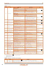
Code

Function

Description

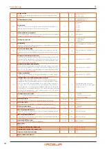
F08

Heating antifreeze 

function

It is automatically activated when the heating probe detects a temperature of 12 °C. The boiler operates at minimum power and is 
deactivated when a temperature of 30 °C is detected.

F09 (1)

DHW antifreeze 

function

It is automatically activated when the DHW probe detects a temperature of 4 °C. The boiler operates at minimum power with 
diverter valve in summer position. It is deactivated when a temperature of 8 °C is detected.

F33 (2)

System air purge cycle 

in progress

It automatically starts when the boiler is first turned on, running for 5 minutes a series of cycles in which the pump is turned on for a 
period of 40 seconds and then turned off for a period of 20 seconds. Regular operation is only permitted at the end of the function. 
It can also be activated during normal operation of the boiler, in the event that the enable of the water pressure switch is lacking, 
when the contact is closed, a 2-minute venting cycle is performed.

FH (1)

Fast H

2

O

It is activated or deactivated by holding down the reset 

 and 

 keys of the 

 DHW side for 7 seconds.

Only for boilers with DHW production.

Not applicable to 100.2 boilers.
Summary of Contents for Caldaia 100.2 Tech

Page 1: ...Powered by natural gas LPG Installation use and maintenance manual Outdoor condensing boiler for heating medium and large buildings Caldaia 55 1 and 100 2 Tech ...

Page 2: ... within this publication are not affected With the aim of continuously improving the quality of its products Robur S p A reserves the right to modify the data and contents of this Installation use and maintenance manual without prior notice Revision A Code D LBR861EN DISPOSAL The appliance and all its accessories must be disposed of separately in accordance with the regulations in force Use of the...

Page 3: ...al installer p 24 4 1 Warnings p 24 4 2 Electrical power supply p 24 4 3 Control device p 24 4 4 Control through optional OCDS006 remote control recommended solution p 25 4 5 Positioning the control system p 25 4 6 Operation via centralised external request p 25 4 7 Operation with external temperature probe optional p 25 5 First start up p 25 5 1 Preliminary checks p 26 5 2 How to access the boile...

Page 4: ...ith the laws in force in the Country of installation Declaration of conformity Upon completing installation the installing firm shall issue to the owner client the appliance s workmanlike conformity declaration according to national local reg ulations in force and the manufacturer s instructions provisions Packing Packing items plastic bags polystyrene foam nails etc must be kept out of the reach ...

Page 5: ...ials paper diluents paints etc near the appliance Limescale and corrosion Depending on the chemical physical properties of the system water limescale or corrosion may damage the appliance Check system sealing Avoid frequent top ups Acid flue gas condensate Discharge the acid condensate of combustion flue gas in compliance with current exhaust regulations Switching the appliance off Disconnecting t...

Page 6: ...ustion products ex haust Fire safety and prevention Any other applicable law standard and regulation III 3 EXCLUSIONS OF LIABILITY AND WARRANTY Any contractual or extra contractual liability of the man ufacturer for any damage caused by incorrect installa tion and or improper use and or failure to comply with regulations and with the manufacturer s directions in structions shall be disclaimed In p...

Page 7: ...in order to meet the requirements of Italian regulations with the exception of the installation of any expansion tank in addition to that already supplied and the gas shut off valve The installation of the devices and the connection to the electrical network must be subject to the safety regula tions for devices containing hot liquids under pressure in compliance with the provisions regulations in...

Page 8: ...1 Side resting on the installation wall 273 93 82 89 5 166 172 227 241 R G A SC V 1 Figure 1 3 Caldaia 100 2 dimensions 350 160 590 977 730 Figure 1 4 Caldaia 100 2 hydraulic connections bottom panel view A Delivery Ø 1 1 2 M R Return Ø 1 1 2 M G Gas Ø 1 M SC Condensate drain V Safety valve drain 1 Side resting on the installation wall R SC 93 162 67 155 180 85 310 215 195 320 SC G A 1 V ...

Page 9: ...densate drain hose 18 Water pressure switch 19 Condensate drain siphon 20 Expansion tank 21 System drain tap 22 Inspection well 23 Gas shut off valve sensing bulb thermowell 24 INAIL approved manual reset lock thermostat 25 INAIL approved maximum pressure lock switch 26 INAIL approved minimum pressure lock switch 27 Pressure gauge connection tap with test flange and shock absorber pipe 28 INAIL co...

Page 10: ...iphon 21 INAIL approved manual reset lock thermostat 22 INAIL approved thermometer 23 INAIL approved minimum pressure lock switch 24 INAIL approved maximum pressure lock switch 25 Pressure gauge connection tap with test flange and shock absorber pipe 26 INAIL compliant pressure gauge 27 System delivery connection 28 System return connection 29 INAIL approved safety valve 30 Expansion tank 31 Gas s...

Page 11: ...nsion tank 24 INAIL approved safety valve 25 Inspection well 26 Gas shut off valve sensing bulb thermowell 27 INAIL approved manual reset lock thermostat 28 INAIL approved maximum pressure lock switch 29 INAIL approved minimum pressure lock switch 30 Pressure gauge connection tap with test flange and shock absorber pipe 31 INAIL compliant pressure gauge 32 In line shut off valve 33 System delivery...

Page 12: ... approved safety valve 25 Inspection well 26 Gas shut off valve sensing bulb thermowell 27 INAIL approved manual reset lock thermostat 28 INAIL approved thermometer 29 INAIL approved minimum pressure lock switch 30 INAIL approved maximum pressure lock switch 31 Pressure gauge connection tap with test flange and shock absorber pipe 32 INAIL compliant pressure gauge 33 In line shut off valve 34 Syst...

Page 13: ...protection IP X5D Installation data Gas consumption G20 natural gas nominal m h 5 29 10 59 G25 nominal m h 6 15 12 30 G25 3 nominal m h 6 01 12 03 G30 nominal kg h 3 94 7 88 G31 nominal kg h 3 88 7 77 Water fitting type M thread 1 1 4 1 1 2 Gas connection type M thread 1 Flue gas exhaust diameter Ø mm 80 100 residual head Pa 100 CO2 percentage in fumes Nominal heat input G20 9 3 9 2 G25 9 2 9 1 G2...

Page 14: ...2 circulators 0 0 5 1 0 1 5 2 0 2 5 3 0 3 5 0 0 2 0 4 0 6 0 8 1 0 2 0 4 6 8 10 12 14 0 1 2 3 4 5 6 7 8 0 10 20 30 40 50 60 70 80 0 0 5 1 0 1 5 2 0 2 5 3 0 3 5 4 0 4 0 0 20 40 60 3780 25PWM1 4270 15 PWM1 4770 5 PWM1 3280 35PWM1 2780 45PWM1 2280 55PWM1 1780 65 PWM1 1290 75PWM1 m ax p kPa H m P1 W Q m h Q l s Q Igpm Q m h max 790 85 PWM1 Figure 1 10 Boiler pressure drop curve boiler INAIL equipment 0...

Page 15: ... Connector for optional room thermostat SRi Heating return probe SPM Male plug INAIL INAIL safety appliances PRM Minimum pressure switch PB Maximum pressure switch TB Lock thermostat L Line N Neutral ne Black ce Light blue ma Brown ar Orange gi Yellow bi White gr Grey 11 10 9 8 7 12 13 14 15 16 17 M12 M9 M7 M5 M2 M4 M8 M10 M15 M16 1 2 3 4 57 61 60 59 58 44 43 42 41 40 39 38 37 36 35 34 33 32 31 30...

Page 16: ...probe SC Manifold probe EV Blower PA Air pressure switch TF Flue gas thermofuse SRi Heating return probe ce Light blue ma Brown gi Yellow bi White gr Grey ma ce ma ce ma ce ma gi bi gr EV ce ma ce ma EA VG Tra ER TS TF SR ce ma ma ce 11 10 9 8 7 12 13 14 15 16 17 M12 M9 M7 M5 M2 M4 M8 M10 M15 M16 1 2 3 4 57 61 60 59 58 44 43 42 41 40 39 38 37 36 35 34 33 32 31 30 29 28 27 26 62 63 64 65 66 67 68 5...

Page 17: ...fety appliances PRM Minimum pressure switch PB Maximum pressure switch TB Lock thermostat ne Black ce Light blue ma Brown ar Orange gi Yellow bi White gr Grey 2 S c h e m a e l e t t r i c o _ R 1 K 1 0 0 R A I N _ f o r m a t o ma ce ma ce ma ce ma gi bi gr EV ce ma ce ma EA VG Tra ce ma ER TS TF SR ar ar ce ma ma ce ne ne Pacq 11 10 9 8 7 12 13 14 15 16 17 M12 M9 M7 M5 M2 M4 M8 M10 M15 M16 1 2 3...

Page 18: ...ust take place outside respecting the dis tances indicated in Figure 2 1 p 18 and in any case at a height from the floor of no more than 3 metres Figure 2 1 Minimum clearance distances A 200 mm B 500 mm H 1000 mm X 200 mm Y 200 mm 3 HEATING ENGINEER 3 1 WARNINGS 3 1 1 General warnings Read the warnings in Chapter III 1 p 4 providing im portant information on regulations and on safety Compliance wi...

Page 19: ...he standard circulator must grant the nominal water flow required for the cor rect operation of the heating system B of the following data Caldaia 55 1 Tech nominal flow at the maximum availa ble head 2150 l h Caldaia 100 2 Tech nominal flow at the maximum avail able head 4300 l h Residual pressure head at nominal flow rate 2 5 m w c 3 3 1 System connections Connect the water pipes between the boi...

Page 20: ...olly valve 2 Tap 2 1 3 3 2 1 System water characteristics Responsibility of the user operator installer The installer operator and user must assure system wa ter quality Table 3 2 p 20 Failure to comply with the manufacturer s guidelines may affect operation integri ty and life of the appliance voiding the warranty In order to avoid any scale or deposits on the primary exchanger the water in the s...

Page 21: ...PF in Figure 5 8 p 32 which must be connected to the combustion chamber after having interposed the silicone gasket supplied for the protection against weathering For the Caldaia 55 1 Tech after installing the flanged socket it is important to check the correct positioning of the gasket G positioned on the combustion chamber Figure 3 5 p 21 Incorrect positioning of the gasket G can compromise the ...

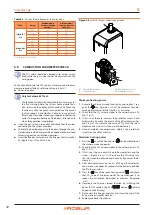
Page 22: ... Ø 80 mm 3 17 5 elbow 45 Ø 80 mm 1 4 7 8 Caldaia 100 2Tech extension pipe Ø 100 mm length 1000 mm 1 6 8 elbow 90 Ø 100 mm 3 24 elbow 45 Ø 100 mm 1 6 11 3 5 PUMP ANTIFREEZE AND ANTI LOCK FUNCTION Antifreeze function If the delivery temperature detected by the temperature probe falls below 12 ºC antifreeze temperature ON the control board starts the circulation pump and the ignition of the burner at...

Page 23: ... FR 20 HU 25 I2L FR 25 RO 20 I2E DE PL RO 20 I3B P AL AT BG BE CY CZ DE DK EE FI FR GB GR HR HU IT LT MT NL NO RO SE SI TR 30 PL 37 AT CH DE SK CY CZ 50 FR 50 I3P AT BE CH CZ DE ES FR GB HU IS NL SK 50 AL BE BG CH CZ ES FR GB GR HR IE IT LT NL LV MK PL PT SI SK TR 37 AT CZ DE NL RO 30 The appliance gas supply pressure both static and dynamic must comply with the values in the Table with a toleranc...

Page 24: ... is forbidden to use gas pipes as earthing Cable segregation Keep power cables physically separate from signal ones Do not use the power supply switch to turn the ap pliance on off Never use the external isolation switch to turn the appli ance on and off since it may be damaged in the long run occasional blackouts are tolerated To switch the appliance on and off use only the control device provide...

Page 25: ...he centralised activation or deactivation of several boilers For the electrical connection of the external request follow the instructions below 1 Remove the boiler front panel Paragraph 5 2 p 26 2 Unscrew the two screws and remove the terminal block cov er plate Figure 4 2 p 25 3 Connect the external request to the terminal block 4 After the operation reassemble the cover plate and then the front...

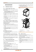
Page 26: ...on conformities the user installer is bound to perform any corrective procedures required by the TAC After performing the remedial actions the installer s responsi bility if the TAC deems that safety and conformity conditions are in place first start up may be effected 5 2 HOW TO ACCESS THE BOILER For most control and maintenance operations it is necessary to remove one or more panels of the boile...

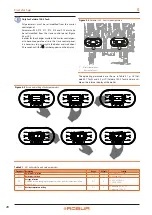
Page 27: ...ing screws 2 Hooks only on slave panel A Master control panel B Slave control panel C Cover C 2 2 2 2 1 1 B 1 1 1 1 A 5 4 ELECTRONIC BOARD PARAMETERS SETTING Before commissioning the operation of the device to the user the operating parameters must be set or simply checked To access the parameters menu and adjust the value of the de sired parameter follow the procedure described below refer to Fig...

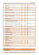
Page 28: ...sition 1 Master control panel 2 Slave control panel 2 1 The operating parameters are shown in Table 5 1 p 28 Cal daia 55 1 Tech and 5 2 p 29 Caldaia 100 2 Tech and are visi ble on the internal display of the boiler Figure 5 5 Access and setting of boiler parameters Table 5 1 55 1 boiler electronic board parameters Parameter Description Range Default Setting P00 Boiler model selection 0 10 10 10 Ca...

Page 29: ...lue see Figure 5 6 p 31 The choice of the curve is determined by the maximum delivery temperature Tm and the minimum outdoor temperature Te taking into account the degree of insulation of the house The values of the delivery tempera tures Tm refer to standard systems 30 80 C or floor systems 25 45 C The type of system can be set using parameter P03 0 30 15 The numbering of the value corre sponds t...

Page 30: ...ing to the set power parameter P00 and the type of gas parameter P02 P10 203 Value in hertz 1 Hz 30 RPM P16 Setting the climate curve only with outdoor probe connected An outdoor temperature probe may be connected and acts by automatically changing the delivery temperature according to the measured outdoor temper ature The extent of the correction depends on the set Kd heating control value see Fi...

Page 31: ...Kd Heating control value Te C 35 30 25 20 15 10 75 80 45 MAX Tm C 5 0 5 10 65 55 60 50 40 45 35 30 30 15 20 25 MIN 35 70 Kd 0 Kd 5 Kd 15 Kd 20 Kd 25 Kd 30 Kd 10 Figure 5 7 Heat input blower frequency diagram Ti Thermal input Freq Frequency G30 G20 G25 G25 3 G31 0 5 10 15 20 25 30 35 40 45 50 55 35 50 65 80 95 110 125 140 155 170 185 200 215 230 245 Ti kW Freq Hz ...

Page 32: ...cket for flue gas analysis and gas valve PF Flue gas analysis socket A Protection screw 1 Gas flow adjustment screw 2 Offset adjustment screw PF 1 2 A Minimum heating power 1 Activate the chimney sweep function by pressing for 7 sec onds the key Figure 6 1 p 34 The maximum time be fore being forced out of the function is 15 minutes 2 Check that the CO2 value complies to the value shown in Ta ble 1...

Page 33: ... Set the boiler to operate with the new type of gas chang ing the value of parameter P02 gas type selection from the control panel Paragraph 5 4 p 27 8 Proceed to the adjustment of the CO2 value as described in Paragraph 5 5 p 32 9 Replace the sticker indicating the gas type on the appliance with the sticker for the new gas type Figure 5 9 Gas changeover 1 Bushing fixing screw 2 Venturi fastening ...

Page 34: ...in active As it is harmful to the appliance it is essential to avoid switching off the appliance by removing the power supply to the external module For the antifreeze and pump anti lock functions to be active the boiler must be left powered 5 9 PROLONGED PERIODS OF INACTIVITY To switch off the unit select the OFF mode using the key Figure 6 1 p 34 In this way the appliance is in standby mode symb...

Page 35: ...ch This may be harmful and dangerous for the appliance and for the system 6 2 PRELIMINARY CHECKS Checks before switching on Before switching on the appliance ensue that Gas valve open Appliance electrical power supply main switch ON The fumes exhaust duct is free and correctly connected to the fumes exhaust system The hydraulic circuit has been filled If this is not the case fill the system accord...

Page 36: ... the key Figure 6 1 p 34 The info code will be displayed on the left side of the screen and its value will be displayed on the centre of the screen 2 To scroll through the list of displayable data use the and keys of the heating side 3 Press the key to exit the Info menu Tables 6 1 p 36 and 6 2 p 36 show the list of Info menu dis playable data Table 6 1 Caldaia 55 1 List of displayable data from m...

Page 37: ...re inside the hydraulic circuit lower than 0 3 bar which can be seen through the pressure gauge located on the instrument panel inside the boiler it is necessary after having identified and solved any leaks on the circuit to proceed with the restoring the correct amount of water with glycol if needed as indicated in Paragraph 3 3 p 19 8 2 ERROR CODES To display the last 5 fault codes from the most...

Page 38: ...heck the flue exhaust duct Manual reset press key 1 Pressure switch disconnected Check the electrical connection Pressure switch fault Replace E15 Return probe fault Probe fault or out of calibration nominal resist ance 10 KΩ at 25 C Replace Automatic Probe connector wet or disconnected Check the electrical connection E16 Blower fault Blower board fault Replace Automatic Blower fault Replace Power...

Page 39: ...hen a temperature of 8 C is detected F33 2 System air purge cycle in progress It automatically starts when the boiler is first turned on running for 5 minutes a series of cycles in which the pump is turned on for a period of 40 seconds and then turned off for a period of 20 seconds Regular operation is only permitted at the end of the function It can also be activated during normal operation of th...

Page 40: ...0 kW Standby heat loss P stby 0 059 kW At part load elmin 0 016 kW Ignition burner power consumption P ign 0 kW In standby mode P SB kW Annual energy consumption Q HE 154 5 GJ Sound power level indoors L WA 52 4 dB Additional information required by COMMISSION REGULATION EU No 813 2013 Table 1 Emissions of nitrogen oxides NO x 51 mg kWh COMMISSION DELEGATED REGULATION EU No 811 2013 Low temperatur...

Page 41: ...load elmax 0 040 kW Standby heat loss P stby 0 100 kW At part load elmin 0 020 kW Ignition burner power consumption P ign 0 kW In standby mode P SB kW Annual energy consumption Q HE 308 0 GJ Sound power level indoors L WA 52 4 dB Additional information required by COMMISSION REGULATION EU No 813 2013 Table 1 Emissions of nitrogen oxides NO x 52 mg kWh COMMISSION DELEGATED REGULATION EU No 811 2013...

Page 42: ......

Page 43: ......

Page 44: ...ch development and promotion of safe environmentally friendly energy efficiency products through the commitment and caring of its employees and partners Robur S p A advanced technologies for climate conditioning via Parigi 4 6 24040 Verdellino Zingonia BG Italy 39 035 888111 F 39 035 884165 www robur it robur robur it ...

Reviews: