Features and technical data
Installation, use and maintenance manual – Caldaia 55.1 and 100.2 Tech
7
1
1
FEATURES AND TECHNICAL DATA
1.1
FEATURES
Operation
The Caldaia 55.1 and 100.2 Tech units have been designed and
built to meet the needs of space heating. These boilers (external
modules) can also be installed outdoors.
The appliance operation will be controlled by an external re-
quest (chronothermostat, room thermostat or another opera-
tion request) or by the remote control to be installed inside the
heated room.
When the heating service is requested, detected by the external
request or by the remote control, the electronic board starts the
circulation pump, the blower and then the burner.
When the burner starts up, the flame detector checks that the
burner has ignited; in the event of a lack of flame, the electronic
control unit stops the appliance and indicates the block. Reset-
ting is manual.
In the event of abnormal overheating of the delivery, the boiler
is switched off. The limit thermostat has manual reset.
Mechanical and thermo-hydraulic components
▶
Integrated spiral single tube stainless steel heat exchanger
(2 heat exchangers for Caldaia 100.2 Tech).
▶
Premix modulating burner with 1:9 ratio.
▶
Automatic air vent valve.
▶
High efficiency modulating water pump.
▶
System drain tap.
▶
Water temperature probe.
▶
Condensate drain siphon.
Control and safety devices
▶
Flue safety thermal fuse.
▶
Gas solenoid valve.
▶
Safety thermostat.
▶
Safety appliances kit approved by INAIL; for further details
see specific Paragraph at
INAIL safety appliances
The boiler is supplied with an INAIL approved safety applianc-
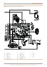
es kit (see Figure 1.2
p. 8 and Figure 1.7 p. 11), created in
order to meet the requirements of Italian regulations, with the
exception of the installation of any expansion tank in addition to
that already supplied and the gas shut-off valve.
The installation of the devices and the connection to the
electrical network must be subject to the safety regula-
tions for devices containing hot liquids under pressure in
compliance with the provisions regulations in force.
It is not allowed to reuse any type of device previously
disassembled from another plant.
The calibration report of the approved safety valve and the cer-
tificates of the control, regulation and safety devices are con-
tained in the packaging of the components themselves.
The kit is composed as follows:
▶
INAIL approved safety valve calibrated at 2,5 bar, positive
action, depending on the installed power, accompanied by
INAIL calibration report and EC approval mark.
▶
Well for INAIL control thermometer.
▶
INAIL approved manual reset lock thermostat.
▶
Thermal switch with declaration of conformity, copy of the
INAIL type approval certificate and instructions.
▶
Sensitive element thermowell for gas shut-off valve.
▶
INAIL approved thermometer with scale 0-120 °C.
▶
INAIL approved pressure lock switch, working range: 1÷5
bar; standard operating pressure 3 bar, acting on the pres-
sure of the relative circuit, accompanied by a document in-
cluding a declaration of conformity, a copy of the INAIL ap-
proval certificate and instructions.
▶
Pressure gauge connection tap with flange for control pres-
sure gauge.
▶
Shock absorber pipe.
▶
INAIL-compliant pressure gauge, working range: 0÷4 bar.
▶
INAIL approved 0,5 bar minimum pressure switch, acting on
the pressure of the relevant circuit, accompanied by a doc-
ument including a declaration of conformity, a copy of the
INAIL approval certificate and instructions.
1.2
DIMENSIONS
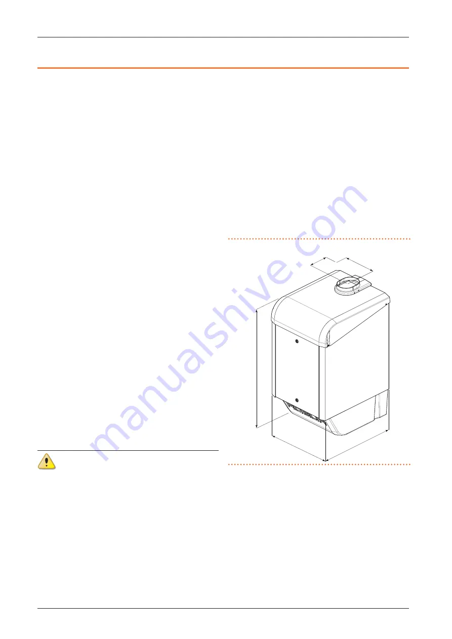
Figure 1.1
Caldaia 55.1 dimensions
480
870
582
240
144


