Diagnostics
Installation, use and maintenance manual – Caldaria Con export
51
8
8
DIAGNOSTICS
In the event of a malfunction of the appliance, before contacting
the TAC, make sure that:
▶
There is a full electricity supply.
▶
The gas is supplied.
▶
The gas pressure is within the indicated limits.
▶
The remote control (if any) is set so that the appliance is
switched on and the appliance does not signal a fault.
8.1
SYSTEM PRESSURE RESTORE
In case of malfunction of the appliance, with pressure inside the
hydraulic circuit lower than 0,3 bar, which can be seen through
the pressure gauge located on the instrument panel inside the
boiler, it is necessary, after having identified and solved any leaks
on the circuit, to proceed with the restoring the correct amount
of water (with glycol, if needed), as indicated in Paragraph
3.3
8.2
ERROR CODES
To display the last 5 fault codes, from the most recent in chrono-
logical order, activate the off mode using the
key (Figure
6.1
p. 47) and press and hold the
key for 5 seconds.
▶
To scroll through the list of stored faults, use the
and
keys of the heating side
.
▶
To reset the fault history, press the reset key
.
▶
To exit the display press the
key.
Only for Caldaria 100.2
The fault codes are shown only in the display of the mas-
ter control panel (detail 1 of Figure 5.4
p. 36).
In the event of faults that are not common to both units,
the fault message code is displayed with the prefix 01 or
02, which indicates in which unit the fault is present (01
= master unit, 02 = slave unit).
In the event of failure of both appliances, the display
will show only the most severe code. To display the next
code, press the
key of the DHW circuit
. After re-
solving the most severe code, the display will show the
next code alternating with the collector temperature.
When a fault code represents an anomaly common to
both units (such as E04, E78, E06, E99) it is preceded by
the word E(x), where (x) will be the number of the chron-
ological order in the last 5 reports.
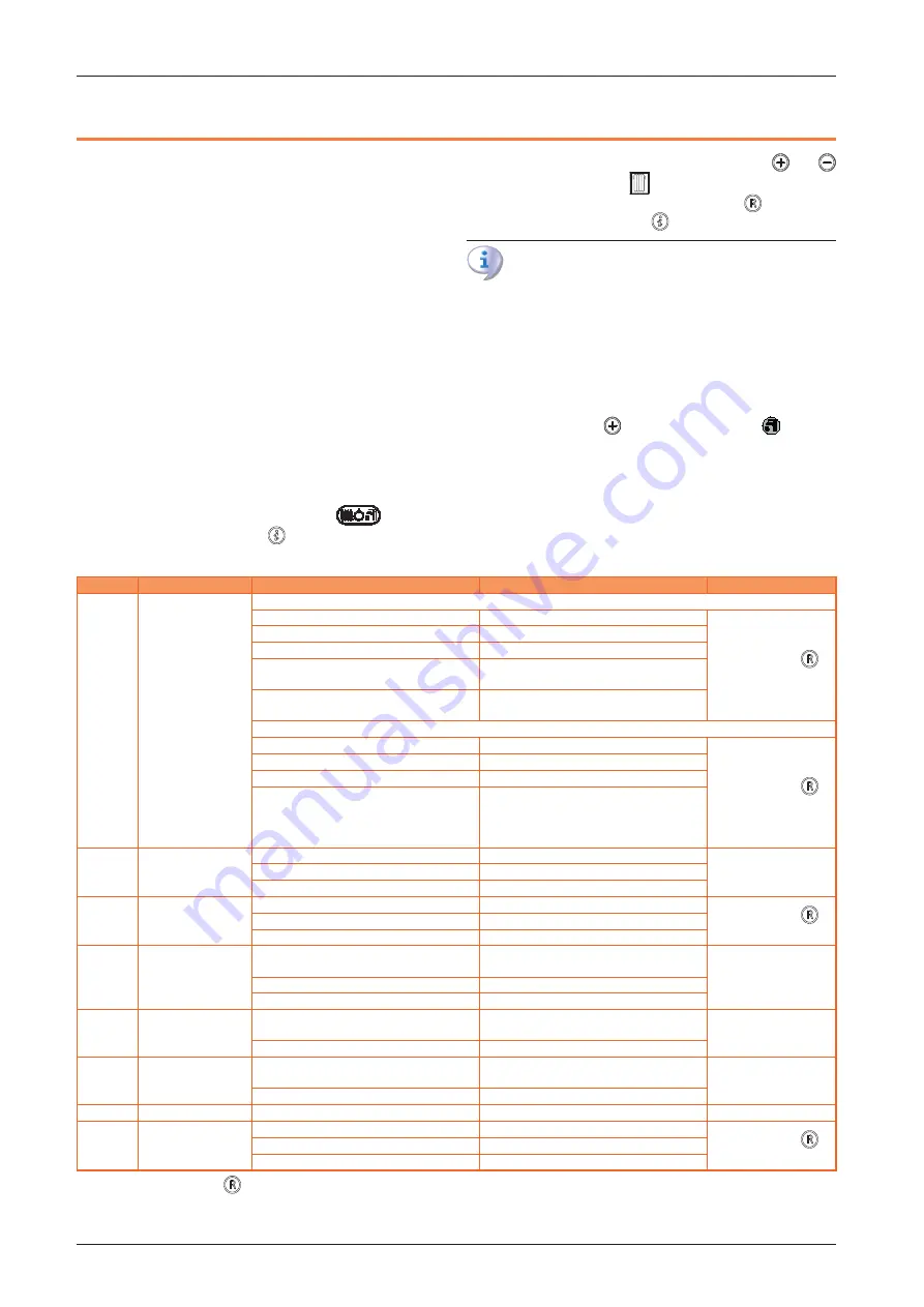
Table 8.1
Error codes
Code
Fault
Possible cause
Remedial action
Reset
E01
Flame lockout
Without flame ignition
No gas supply
Check the gas supply network
Manual reset (press
key) (1)
Broken or badly positioned ignition electrode
Replace
Gas valve fault
Replace
Slow ignition set too low
Adjust the minimum pressure to the burner or
slow ignition
Inlet pressure of gas valve too high (only for LPG
supply)
Check the maximum burner pressure
With flame ignition
Power supply with phase and neutral inverted
Connect the power supply correctly
Manual reset (press
key) (1)
Flame detector fault
Replace
Detection electrode cable disconnected
Check the electrical connection
Phase-to-phase electric current
If the voltage measured between neutral and
earth is almost the same as the one measured
between phase and earth, eliminate the
dispersions
E02
Safety thermostat trip
(95 °C)
Hydraulic circuit overheating
Remove the cause of the lack of heat exchange
Automatic
Thermostat cable broken or disconnected
Check the electrical connection
Thermostat fault
Replace
E03
Flue safety thermal
fuse (102 °C)
Hydraulic circuit overheating
Remove the cause of the lack of heat exchange
Manual reset (press
key) (1)
Thermal fuse fault
Replace
Thermal fuse cable disconnected
Check the electrical connection
E04
Low system water
pressure
Insufficient water pressure in the system (less
than 0,3 bar)
Load the system at the required pressure
Automatic
Water pressure cable disconnected
Check the electrical connection
Water pressure switch fault
Replace
E05
Heating probe fault
Probe fault or out of calibration (nominal resist-
ance 10 KΩ at 25 °C)
Replace
Automatic
Probe connector wet or disconnected
Check the electrical connection
E06 (2)
DHW probe fault
Probe fault or out of calibration (nominal resist-
ance 10 KΩ at 25 °C)
Replace
Automatic
Probe connector wet or disconnected
Check the electrical connection
E10 (3)
False safety trip
Incorrect setting of parameter P32 to value 1
Set parameter P32 to 0
Automatic
E14 (4)
Air pressure switch
Exhaust duct obstructed
Check the flue exhaust duct
Manual reset (press
key) (1)
Pressure switch disconnected
Check the electrical connection
Pressure switch fault
Replace
1
In the Caldaria 100.2 press the
key on the master control panel.
2
Only for boilers with DHW production.
3
Not applicable to Caldaria 100.2.
4
Only for Caldaria 100.2.
Summary of Contents for Caldaria 100.2 Condensing+ export
Page 55: ......


