Heating engineer
Installation, use and maintenance manual – Caldaria Con export
21
3
3
HEATING ENGINEER
3.1
WARNINGS
3.1.1
General warnings
Read the warnings in Chapter III.1
p. 4, providing im-
portant information on regulations and on safety.
Compliance with installation standards
Installation must comply with applicable regulations in
force, based on the installation Country and site, in mat-
ters of safety, design, implementation and maintenance
of:
heating systems
gas systems
flue gas exhaust
flue gas condensate discharge
Installation must also comply with the manufacturer's
provisions.
3.2
BOILER INSTALLATION
To facilitate assembly, the boiler is equipped with a jig and a
frame (Caldaria 55.1 and Caldaria 100.2), that allow to prepare
in advance the connections to the pipes with the possibility of
installing the boiler when the masonry work is complete.
Follow the instructions below for installation.
3.2.1
Caldaria 35
1. Fix the mounting jig of the external module to the instal-
lation wall, matching, if already present, the Ø 80 mm hole
for the passage of water pipes and electrical cables with the
shape of the relative hole (Ø 80 mm) indicated on the jig.
At this point, in correspondence with the relative shapes of
the holes indicated on the jig, trace the following points for
drilling on the wall: 3 fixing holes (Ø 10 mm) and 1 lower hole
(moved to the right) Ø 10 mm.
2. Remove the mounting jig from the wall and drill the holes
marked out in the previous point: for the 3 upper holes (Ø
10 mm) for fixing the support bracket and the one for the
frame of the external module, a depth of 90 mm is sufficient;
the hole (Ø 80 mm) must be drilled for the entire thickness
of the wall.
3. Insert a plastic pipe through the wall into the hole (Ø 80
mm), cut to size.
4. Position the support bracket of the external module in corre-
spondence with the upper holes made (Ø 10 mm, depth 90
mm) and secure it with the supplied wall plugs.
5. Lift the boiler and hook it to the support bracket.
6. Secure the boiler permanently to the wall, fastening the rear
panel by means of the third wall plug supplied.
3.2.2
Caldaria 55.1 and 100.2
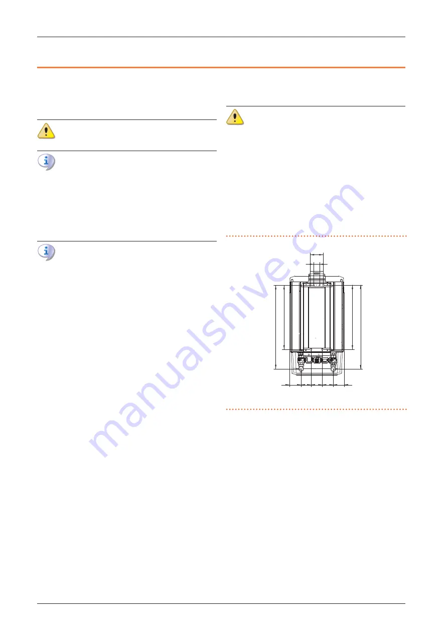
1. Using a spirit level, fix the jig to the wall where the boiler is to
be installed and mark the points for inserting the wall plugs
and the points of the system's delivery and return connec-
tions (Figure 3.1
p. 21 for Caldaria 55.1 and 3.2 p. 22 for
Caldaria 100.2)..
2. Drill the holes and fix the frame to the wall (Figure 3.3 p. 22).
3. Hang the boiler using the slots on the frame (Figure
p. 22).
In order to avoid condensation stagnation inside the
boiler, it is necessary to tilt the boiler outwards by 1÷1.5°
(Figure 3.4
4. Unscrew the fixing screws of the lower bracket ensuring the
free sliding of the bracket with respect to the boiler (Figure
p. 22).
5. Tilt the boiler about 1÷1.5° vertically (Figure 3.4 p. 22). To
lock the boiler position, tighten the fixing screws of the low-
er bracket.
6. Make sure that the boiler is firmly fixed to the wall.
7. Make the hydraulic and electrical connections as specified in
the relevant paragraphs.
8. Reassemble the fitting cover, disassembled during the pre-
vious operations.
Figure 3.1
Caldaria 55.1 mounting jig
A
Outlet Ø 1 1/4" M
R
Inlet Ø 1 1/4" M
115
99
49
561
564
737
732
87
96
95
103
A
R
Summary of Contents for Caldaria 100.2 Condensing+ export
Page 55: ......


