Installation and user manual
Error! Use the Home tab to apply
Titolo 1 to the text that you want to
appear here.
10
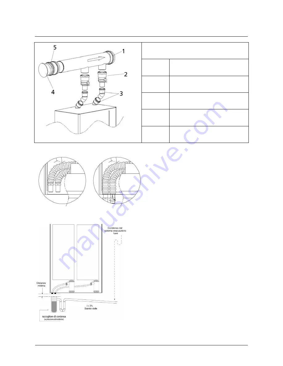
Figure 9
1
DN125 manifold
2
Non-return device (Clapet)
3
45° bend
4
DN125 Tap
5
DN125 joint
3.6 Condensate discharge
Figure 10
CALDARIA CONDENSING 100 allow the
condensate discharge using the two little pipes
shown in Figure 10. In the packing these pipes are
in the shell (as indicated in Figure 10) so, first of all,
it’s necessary to extract them by using the two
holes and then fix them with the two screwed rings.
The condensate water produced by thermal
assembly Caldaria Condensing 100 during its
normal operation shall be discharged at
atmospheric pressure, i.e. by dripping into a
siphon-shaped container (
) connected as described in the following procedure:
- Create a drip pan under the condensate discharge
system (see position on the installation template);
- Connect the drip pan to the sewage system by
means of a siphon.
- Insert a neutraliser if required by the applicable
law.
The drip pan shall be created and installed in
accordance with the applicable technical standards
(see par. 1.1).
It is advisable to use plastic pipes (PP) to create the
condensate discharge system. Never use copper
pipes, as the condensate would rapidly damage
them.
Summary of Contents for CALDARIA CONDENSING 100
Page 38: ...Installation and user manual...


