


Installation and user manual
Error! Use the Home tab to apply
Titolo 1 to the text that you want to
appear here.
12
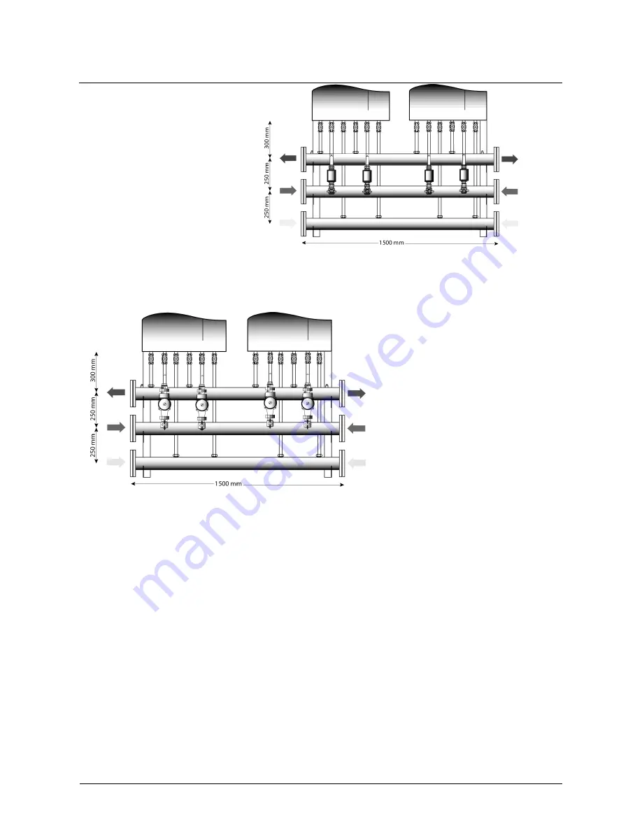
In
Figure 15 and
Figure 16 is shown the kit for two
Caldaria Condensing 100 composed
by the following items :
N°1 gas collector Ø3”
N°1 delivery collector Ø3”
N°1return collector Ø3”
The collectors arrive until 400 kW in
an
installation
of
four
Caldaria
Condensing 100. Each collector is
fitted with 2 branch pipe, at whose
ends are two 1' taps for delivery and
return collectors, and two ¾' taps for
the gas collector.
In this case it is also possible to
complete the connections using a
two way valve kit (see
Figure 15) or using a pump kit (see
Figure 16).
Figure 15
Figure 16
3.7.1
Operating pressure
The maximum operating pressure is
6 bar, its minimum operating
pressure is 0.5 bar. Each unit has a
safety valve at 5.5 bar
3.7.2
Filling and emptying
The
boiler
should
be
filled
connecting the water network to any
system point.
The boiler should be emptied using
the relevant valves in the relevant
system points.
4 Installation drawings
A plant scheme must be fit for the technical boiler features: so it’s possible to utilize in the better way boiler’s
efficiency and to keep the plant in good conditions for a long time. The figures below show some possible
solutions for Caldaria Condensing 100 installations schemes.
In the following schemes we can use a connection with a pump for each unit or a connection with a two way
valve for unit. In the first case the unit pump supplies the adequate flow for each unit and the system pumps
are dimensioned for the pressure drops of the system. Figure 17 shows a 150 kW installation with a pump
for each unit. In Figure 18 it is shown a similar system with a header.
Summary of Contents for CALDARIA CONDENSING 100
Page 38: ...Installation and user manual...


