Installation and user manual
Error! Use the Home tab to apply
Titolo 1 to the text that you want to
appear here.
8
3.3 System cleaning
This preventive measure is absolutely required whenever a heat generator needs to be replaced in existing
systems, but it is in any case recommended also on new systems, in order to remove any waste, dirt,
working residues, etc.
To clean the system, if the old generator is still present in the system, it is advisable to:
- Add a descaling additive, such as FERNOX Superfloc 2%, to the system water;
- Have the system operate with the operating generator for approximately 7 days;
- Discharge the system's dirty water and wash once or several times using clean water. If the system is very
dirty, repeat the last procedure one more time.
If the old generator is not present or available, use a pump to circulate the water + additive through the
system for about 10 days and perform a final washing as described in the previous paragraph.
At the end of cleaning operations, before installing boiler Caldaria Condensing 100, it is advisable to add
protection fluid FERNOX MB-1 AT 4% to the system water.
3.4 Gas system
The boiler is prepared for the gas type shown on th
e data plate that is inside the shell. It’s important to verify
the real match between available gas type and the type required by the boiler.
If your gas is a LPG it’s important to verify the regulation of the pressure on the gas line.
The gas change procedure is shown in par. 7.1
“Gas change – Methane-LPG conversion”
3.5 Flue gas system
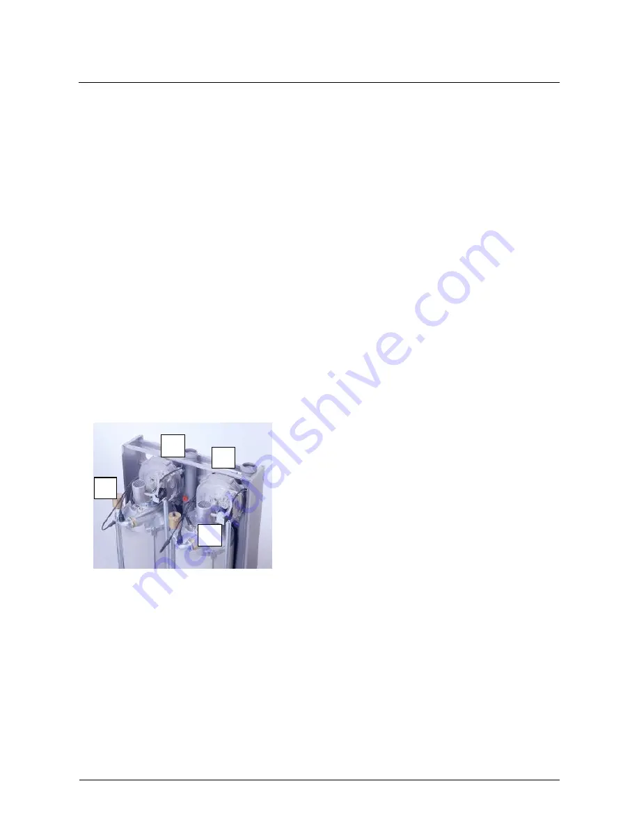
Each heat generator (unit) inside thermal assemblies Caldaria
Condensing 100 has been validated equipped with a self-
extinguishing polypropylene flue gas exhaust system (letter A
in
Figure 7
) with glass-shaped connections.
As for the air supply system, since thermal assemblies
Caldaria Condensing 100 have been validated as type B or
type C assemblies, air can be taken directly from the boiler
room through specific vacuum pipes (letter B in
Figure 7
).
In any case the air supply system has to be made in
compliance with the applicable standards.
3.5.1
Pipe maximum length
Each 50 mm exhaust pipe maximum equivalent length is 30 metres with a maximum 4-metre flow resistance
for each 90° bend.
3.5.2
Installation of one single thermal assembly with flue gas exhaust pipe running inside a cavity
for pipe routing (open chamber operation)
For this type of operation, it should be checked that the cavity's size complies with the applicable standards
(see par. 3.6).
Figure 8
shows the cavity's minimum size for the routing of two flue gas exhaust pipes.
A
Figure 7
A
A
B
B
Summary of Contents for CALDARIA CONDENSING 100
Page 38: ...Installation and user manual...


