background image

Installation and user manual 

Error! Use the Home tab to apply 

Titolo 1 to the text that you want to 

appear here.


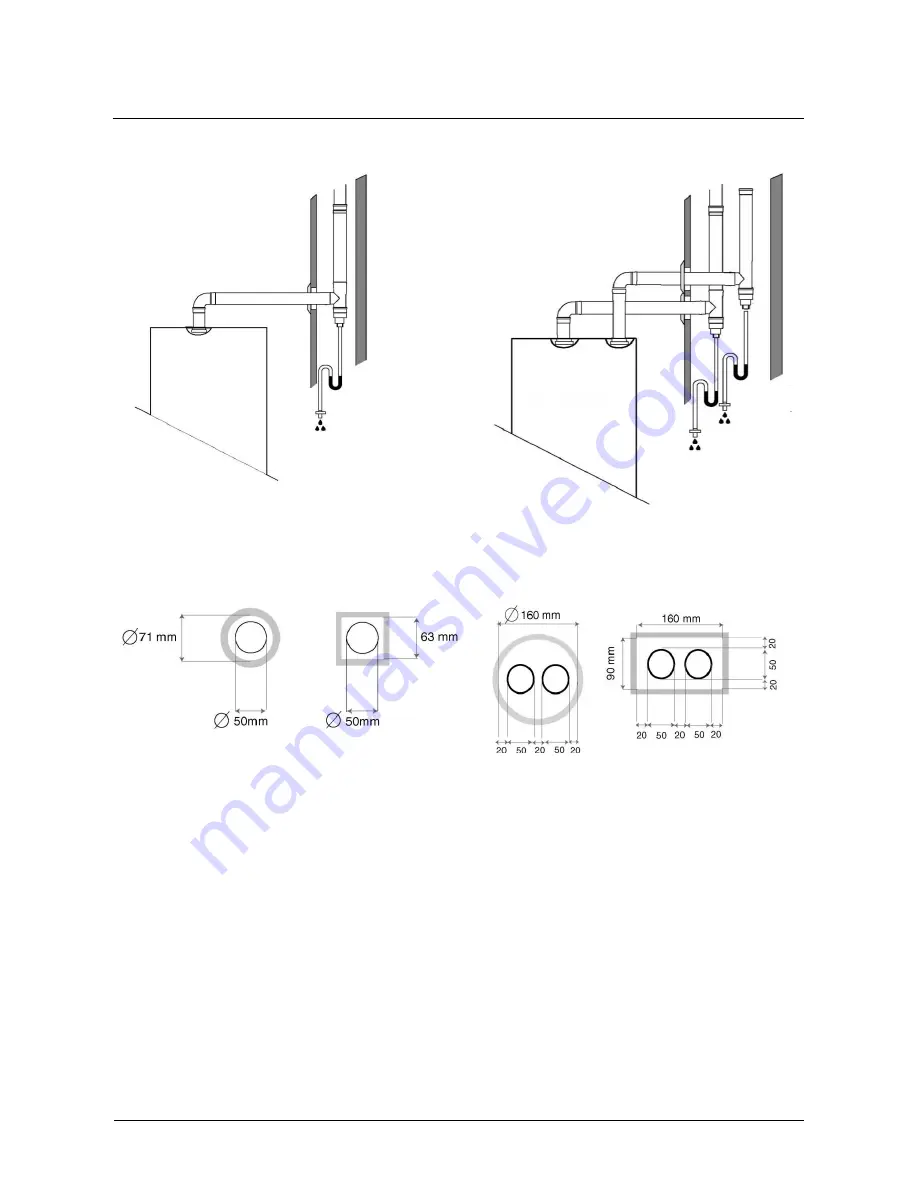
Figure 8 


Should it be necessary to extend the vertical or the horizontal section of the discharge piping to over 4 
metres, create a siphon for condensate drainage at the foot of the pipe. The siphon's useful length must be 
at least 30 cm. (see par. 3.6). 


3.5.3 

Connection to a flue gas manifold  

The flue gas venting system for two or more Caldaria Condensing 100 installed in series can be realized with 
the installation of a polypropylene manifold (it’s optional) with a diameter of 125 mm, with male/female 
connections. 
The collector was conceived to collect the flue gas from the two 50mm pipes of a Caldaria Condensing 100, 
each of which contains a flue gas non-return device.  
If you want to use the collector when several thermal assemblies are installed in series, the minimum 
distance required between the assemblies (150 mm) (see Figure 9) must be complied with.  
In this way, the male end of one of the two collectors will connect more easily to the female connection of the 
nearby collector.  

Summary of Contents for CALDARIA CONDENSING 100

Page 1: ...D LBR571 rev B 15 MCM SDC 006 CALDARIA CONDENSING 100 Instruction manual Installation and use 92 42 CEE UNI EN ISO 9001 2000 UNI EN ISO 14001 2004...

Page 2: ...Power supply 15 5 2 Warnings 16 5 3 Electrical connections 16 5 3 1 5 3 1 Connection to temperature regulation devices 16 5 3 2 Antifreeze protection 16 5 3 3 Pump connection 16 5 3 4 Room Thermostat...

Page 3: ...erature not exceeding 110 C UNI 10845 Italian standard for flue gas venting system for hot water boilers fired with gaseous fuels The company Robur S p A has the certification UNI EN ISO 9001 2000 CAL...

Page 4: ...ing system and system for the production of sanitary hot water with accumulation simultaneously managing three different systems operating at three different temperatures Caldaria Condensing 100 is fi...

Page 5: ...ers Standard condensate discharge system in the boiler Fast connection of water condensate and gas optional collectors with right and left outlet Various thermal modules and the Master control station...

Page 6: ...t the point of sale where the product was purchased NUM DESCRIPTION 1 Packing 2 Product plate 3 Information about model gas type 4 Information about EC mark symbols 5 Lower support structure in polyst...

Page 7: ...ion 3 2 2 Wall mounting WARNING Thermal assemblies Caldaria Condensing 100 series could be installed outdoor 3 2 2 Wall mounting The boiler must be installed on a solid masonry wall by means of hooks...

Page 8: ...plate that is inside the shell It s important to verify the real match between available gas type and the type required by the boiler If your gas is a LPG it s important to verify the regulation of th...

Page 9: ...aldaria Condensing 100 installed in series can be realized with the installation of a polypropylene manifold it s optional with a diameter of 125 mm with male female connections The collector was conc...

Page 10: ...gs The condensate water produced by thermal assembly Caldaria Condensing 100 during its normal operation shall be discharged at atmospheric pressure i e by dripping into a siphon shaped container conn...

Page 11: ...delivery 1 M in Figure 6 System return 1 R in Figure 6 To create the hydraulic connection two kits are available the first one can be used for the installation of one Caldaria Condensing 100 the seco...

Page 12: ...perating pressure is 0 5 bar Each unit has a safety valve at 5 5 bar 3 7 2 Filling and emptying The boiler should be filled connecting the water network to any system point The boiler should be emptie...

Page 13: ...hown in Figure 19 it is necessary to calculate the three pumps for high temperature low temperature and sanitary hot water to guarantee in any case an adequate flow for each circuit and for each unit...

Page 14: ...Installation and user manual Error Use the Home tab to apply Titolo 1 to the text that you want to appear here 14 Figure 19 Figure 20...

Page 15: ...lue for the pressure drop 0 100 200 300 400 500 600 700 800 0 x n 500 x n 1000 x n 1500 x n 2000 x n 2500 x n 3000 x n l h mbar Figure 22 We have to remember that the pump has to supply 2000 l h with...

Page 16: ...the power supply cable break switch off the thermal assembly To replace it contact qualified personnel 5 3 Electrical connections 5 3 1 5 3 1 Connection to temperature regulation devices Caldaria Con...

Page 17: ...Sanitary temperature probe S2 J11 5 6 Flow temperature probe Low SE J11 7 8 External temperature probe T1 J12 9 10 Room thermostat High T2 J12 11 12 Room thermostat Low AI J12 13 14 Analogical device...

Page 18: ...tion of an alarm device A 220 V clear contact block output on the boiler s terminal strip allows to connect an outside sound or visual alarm device capable of highlighting any technical anomalies The...

Page 19: ...ery installation On of the many functions included in Caldaria Condensing 100 electronics allows for the installation of several modules in series to create thermal assemblies having an overall power...

Page 20: ...ase a value S5 Decrement It is necessary to decrease a value S6 Prog OK It is necessary to store a value U2 Luminous display Display information about boiler condition U3 Luminous display Display info...

Page 21: ...atus e g pump not functioning e g pump functioning P 1 0 P 1 1 10 Sanitary circuit pump status e g pump not functioning e g pump functioning P 2 0 P 2 1 11 Secondary pump status e g pump not functioni...

Page 22: ...he display returns to the parameters display mode and the T6 is displayed 6 40 If no procedures are carried out for 10 seconds after that S2 SET ESC has been pressed to modify the set point of the cor...

Page 23: ...C 1 70 5 To exit monitor mode press S2 SET ESC If no procedures are carried out for 5 minutes the boards automatically returns to functioning display 1 80 Trough S3 S3 arrow the following values can b...

Page 24: ...s overall length over 15 metres 7 1 2 Operating instruction 1 Shut any electric supply 2 Close the gas valve 3 Unscrew the two screws to remove the frontal panel 4 Remove the 3 screw from the gas val...

Page 25: ...he maximum power and then change if it s necessary the Venturi regulation 7 Let the boiler arrive to the minimum power by using S5 key 8 On left of the display it will appear a L Low minimum power act...

Page 26: ...ration of a battery with seven burner in cascade In case two blocks are present in an installation having a battery of seven burners i e seven slaves the first is made of 4 burners and the second is m...

Page 27: ...s homologated for safety performances and with a double processor technology Such device allows to continually control both flow temperature and the Dt between flow and return of the battery element M...

Page 28: ...NTC sensor 2 Storage heater with NTC sensor 5 Instant with flow switch 6 Storage heater with thermostat 7 P_dhw_max 1 255 230 Setting the max fan speed for dhw mode 8 T_Dhw_limit 10 C T_Dhw_max 60 Thi...

Page 29: ...1 Attenuation_high 0 C 70 C 0 The Tset is decreased with the attenuation function only if High Temperature thermostat input is open 0 The system is turned off after thermostat opening 1 n The set poin...

Page 30: ...If it is 0 it is used as the system pump 35 T4 frost protection 30 C 15 C 3 Temperature for starting frost protection on T4 If T4 this value or T1 5 C then the pump start If after 10 minutes T1 is not...

Page 31: ...y Titolo 1 to the text that you want to appear here 31 restored EXCEPT GAS TYPE NUMBER par 42 and par 43 settings 42 Flow switch present on the slaves 0 1 1 0 The slave check not for the flow switch 4...

Page 32: ...on 1 15 Max vel ventil max fan speed 230 16 Priorit riscald CH priority 0 17 Temp max CH1 80 18 Temp min CH1 50 19 Diff on CH1 CH1 on hyst 7 20 Diff off CH1 CH1 off hyst 3 21 Attenuaz CH1 CH1attenuati...

Page 33: ...ow water flow or low system pressure 0 5 bar A05 Gas valve coil cut off Gas valve connector false contact Defective gas valve connector Limit thermostat intervention 90 C while burner was on E36 Inter...

Page 34: ...Installation and user manual Error Use the Home tab to apply Titolo 1 to the text that you want to appear here 34 11 Electrical wiring diagram...

Page 35: ...Installation and user manual Error Use the Home tab to apply Titolo 1 to the text that you want to appear here 35...

Page 36: ...full load Tm 50 C 60 40 C 106 1 Efficiency at reduced load 30 80 60 C 98 7 Efficiency at reduced load 30 50 30 C 108 7 Efficiency at reduced load 30 Tm 50 C 60 40 C 106 6 Combustion efficiency 80 60...

Page 37: ...Installation and user manual Error Use the Home tab to apply Titolo 1 to the text that you want to appear here 37 Condensate pipe mm 18...

Page 38: ...Installation and user manual...

Page 39: ...Installation and user manual ROBUR S p A Via Parigi 4 6 24040 Verdellino BG Tel 39 035 888 111 Fax 39 035 4821334 info robur it www robur com...

Reviews: