background image

Installation manual

for System Controller for K18 absorption heat pump

Expansion kit

Summary of Contents for Expansion kit

Page 1: ...Installation manual for System Controller for K18 absorption heat pump Expansion kit ...

Page 2: ...of this Installation manual other than for personal consultation must be previously authorised by Robur S p A The rights of those who have legitimately filed the registered trademarks contained within this publication are not affected With the aim of continuously improving the quality of its products Robur S p A reserves the right to modify the data and contents of this Installation manual without...

Page 3: ... 14 3 2 Temperature sensor connectionp p 15 3 3 Water circulation pump connectionp p 15 3 4 Mixer valve connectionp p 16 3 5 External request signal connection to CSK18 enclosure p 17 4 Commissioning p 17 4 1 Using the QAA75 611 advanced room unit s interface p 17 4 2 Commissioning procedurep p 17 4 3 Functional testsp p 17 4 4 Setting the system to STAND BYp p 18 5 Settings p 19 5 1 Optimising he...

Page 4: ...in the K18 Hy brigas type of unit and consists of an integrated boiler module whereas it is optional in K18 Simplygas units not necessarily supplied by Robur and connected to the plumbing system out side the unit TAC Technical Assistance Centre authorised by Robur DHW domestic hot water III WARNINGS This manual is an integral and essential part of the product and must be delivered to the user toge...

Page 5: ...e n 1 10 pole connector green marked X110 n 1 7 pole connector red marked X150 n 1 10 pole connector grey marked X152 There may also be n 1 3 pole connector green marked X10 which is not used The above parts may also be supplied assembled or partly as sembled together III 4 EXCLUSIONS OF LIABILITY AND WARRANTY Any contractual or extra contractual liability of the man ufacturer for any damage cause...

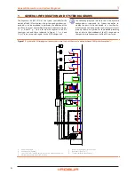
Page 6: ...oller in cluding the parts to be connected to it Ancillary hy draulic components expansion tanks safety valves etc are only shown as a guide for the detailed plumbing layout refer to the handbook of the K18 range and to the specific installation manual of the K18 unit used Figure 1 1 System with K18 Simplygas unit primary water circuit only and three zones auxiliary boiler and DHW production optio...

Page 7: ...ls A Unit K18 Simplygas B Auxiliary boiler optional C check valve to be installed only in the presence of an auxiliary boiler D External water pump only for C0 versions E Decoupling of primary secondary circuits F Room unit 1 QAA75 611 H Room unit 2 and 3 for HC2 and HC3 circuits optionals QAA75 611 or QAA55 110 P ST B9 B3 Q3 B C ST ST GHP CSK18 GHP H E ST F HC1 Q2 Y1 Y2 B1 H HC3 Q20 ST HC2 Q6 Y5 ...

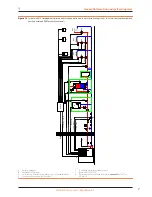
Page 8: ...igas unit primary water circuit only and three zones DHW production optional A K18 Hybrigas unit E By pass section with overpressure valve F Room unit 1 QAA75 611 G Thermostats with timer for zones P A ST B9 B3 Q3 ST CSK18 GHP E K18 CONTROL CABLE HC1 G F Q2 HC3 G Q20 HC2 G Q6 ...

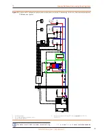
Page 9: ...optionally mixed DHW production optional A K18 Hybrigas unit E Decoupling of primary secondary circuits F Room unit 1 QAA75 611 H Room unit 2 and 3 for HC2 and HC3 circuits optionals QAA75 611 or QAA55 110 P A ST B9 B3 Q3 ST CSK18 GHP E K18 CONTROL CABLE H ST F HC1 Q2 Y1 Y2 B1 H HC3 Q20 ST HC2 Q6 Y5 Y6 B12 For water circuits with a primary circuit only fig 1 1 p 6 and 1 3 p 8 water circulation mus...

Page 10: ...t contain mains cables and those which con tain safety extra low voltage cables and between the two categories of cables inside the enclosure achieve this by following the instructions provided in the Instal lation Manual of the System Controller with regards to the choice of the input holes in the enclosure to use for the mains connections and for the safety extra low volt age SELV ones The CSK18...

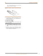
Page 11: ...ollowing into the corresponding sockets af ter having identified them 10 pole connector green X110 7 pole connector red X150 10 pole connector grey X152 even if it is included in the kit DO NOT install the 3 pole green connector X10 If the expansion kit is supplied with the connectors already installed pull out the 3 pole green connector X10 5 Identify the 3 pole green connector X10 left free insi...

Page 12: ...18 enclosure with the Expansion kit installed The additional electrical connections regarding the functions handled by the Expansion kit are made on the included extractable connectors which fit directly into the kit s AVS55 196 electronic board as described in this manual On the other hand unless otherwise expressly specified for the functions available without the Expansion kit re fer to the sys...

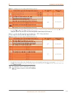
Page 13: ...nd signals connections on the extractable connectors on the right edge of the Siemens RVS55 196 expansion board Table 2 2 SELV signal connections to Siemens AVS55 196 board connectors Function Siemens logo on water circuit diagrams and description Logo on connector Color Connector code Siemens BSB BSB QAA75 QAA55 Room Unit data bus connection 1 X150 Red BPZ AGP5S 07L 109 M BSB QAA75 QAA55 optional...

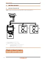
Page 14: ... unit 1 QAA75 611 C D Ambient units 2 and 3 QAA55 110 optional code ODSP004 NOTE Use shielded signal cable 3x0 75 mm2 2x0 75 mm2 for QAA55 110 Maximum total length 400 m Maximum length between controller and room unit 200 m Both room units can also be connected to connector X86 GX1 H3 M H1 1 X86 G M BSB 1 2 3 1 2 1 2 B A C D Table 3 1 QAA75 611 and QAA55 110 optional room unit connection RVS21 826...

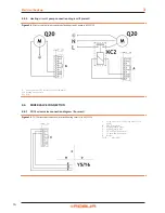
Page 15: ... if heating circuit 2 is mixed Use shielded cable 2 x 0 5 mm up to 40 m 2 x 0 75 mm up to 60 m 2 x 1 0 mm up to 80 m 2 x 1 5 mm up to 120 m 3 3 WATER CIRCULATION PUMP CONNECTION 3 3 1 Heating circuit 2 pump connection diagram if present Figure 3 3 Direct or external relay connection of heating circuit 2 pump to AVS55 196 A Green connector X110 left edge of AVS55 196 board Q6 Heating circuit 2 pump...

Page 16: ...6 board Q20 Heating circuit 3 pump KC2 Relay 3 4 MIXER VALVE CONNECTION 3 4 1 Y5 Y6 mixer valve connection diagram if present Figure 3 5 Y5 Y6 mixer valve connection for mixed heating circuit 2 to AVS55 196 A Green connector X110 left edge of AVS55 196 board B Flow from system C Heating circuit 2 outlet D Heating circuit 2 inlet E Y6 close flow from system F Y5 open flow from system N Neutral Y5 Y...

Page 17: ...the socket on the expansion board and that the ribbon cable has been inserted into the comb con nectors marked X100 on the RVS21 826 and AVS55 196 boards 4 3 FUNCTIONAL TESTS These tests are not strictly necessary however they allow you to quickly identify most problems with the electrical hookup and system anomalies we strongly recommend running them 4 3 1 Testing the inputs and outputs 1 Access ...

Page 18: ... to closed indicat ed by o o o and back NOTE If no external request signal is present this test must indicate closed o o o due to the jumper added during installation 15 If heating circuit 3 or zone 3 is present and an external re quest is hooked up Select parameter 7989 Input signal H31 and actuate the external signal s contact to check that it switches as expected from open indicated by to close...

Page 19: ...dicat ed for heating circuit 1 in the above mentioned paragraph of the system controller Installation manual but using the Time prog heating cooling 3 menu in this case use parameters 540 Preselection 541 546 period settings and 555 Copy 5 1 4 Setting the heating curve slope and min max outlet water setpoints Refer to Paragraph 5 1 4 of the system controller Installation manual 5 1 5 Setting the R...

Page 20: ... 48 Occupancy button device 1 and set it to Heating circuit 1 only You must now configure the second room unit installed in a ref erence room heated circuit 2 Proceed as follows depending on the type of room unit Second room unit type QAA75 611 Proceed as follows working on the second room unit 1 Access the Engineer menu level then the Operator section menu 2 Select parameter 40 Used as and set it...

Page 21: ...unction mixing group 3 and set it to Heating cir cuit 2 Run sensor memorization again as indicated in step 1 ATTENTION This sensor is used only in the presence of the mixed heating circuit 2 otherwise no sensor must be connected to input BX31 If a sensor is connected to this input by mis take remove it then run sensor memorisa tion again as described in step 1 5 If step 4 does not resolve the prob...

Page 22: ... BX34 to which no function is assigned For codes 330 331 332 333 refer to Paragraph 6 1 of the System Controller Installation manual For codes 441 442 443 444 pro ceed as follows 1 Check the configuration a for code 441 Access the Engineer menu level then the Config uration menu select parameter 6391 Sensor in put BX31 check that it is set to the value used by parameter 6455 if not remaining in th...

Page 23: ...ensor cables copper Cross section Max length 0 25 0 5 0 75 1 0 1 5 mm 20 40 60 80 120 m Outputs Relay outputs QX31 QX33 QX35 Current range Switching ON current Total current AC 0 02 2 2 A max 15 A for 1 s max AC 10 A total all 230 VAC outputs Triac output ZX34 Current range Switching ON current Total current AC 0 02 2 2 A On Off operation AC 0 02 1 2 1 2 A speed control max 4 A for 1 s max AC 10 A...

Page 24: ... 888111 F 39 035 884165 www robur it robur robur it 10 03 2017 17MEDSDC006 Code D LBR809 Revision A Robur mission Robur is dedicated to dynamic progression in research development and promotion of safe environmentally friendly energy efficiency products through the commitment and caring of its employees and partners ...

Reviews: