Assembly and installation
Installation manual – Expansion kit
11
2
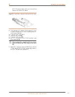
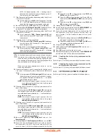
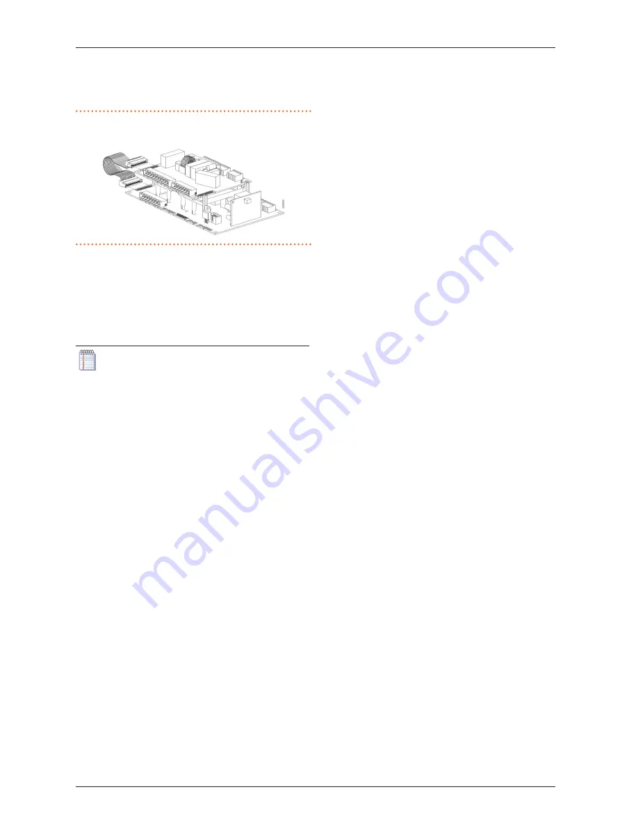
AVS55.196 electronic board; in this case, insert the free
connector into the RVS21.826 board.
Figure 2�3
Detail of ribbon cable connection between the two boards
4� If the expansion kit is supplied with the connectors not yet
installed, fit the following into the corresponding sockets af-
ter having identified them:
▶
10 pole connector, green, X110
▶
7 pole connector, red, X150
▶
10 pole connector, grey, X152
▶
even if it is included in the kit, DO NOT install the 3 pole
green connector X10
If the expansion kit is supplied with the connectors
already installed, pull out the 3 pole green connector
X10�
5� Identify the 3 pole green connector X10 left free inside the
CSK18 enclosure and fit it into the corresponding socket on
the AVS55.196 board of the Expansion kit.

