Electrical hookup
16
3
3.3.2
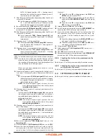
Heating circuit 3 pump connection diagram (if present)
Figure 3�4
Direct or external relay connection of heating circuit 3 pump to AVS55.196
A
Green connector X110 (left edge of AVS55.196 board)
Q20 Heating circuit 3 pump
KC2 Relay
3.4
MIXER VALVE CONNECTION
3.4.1
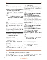
Y5/Y6 mixer valve connection diagram (if present)
Figure 3�5
Y5/Y6 mixer valve connection (for mixed heating circuit 2) to AVS55.196
A
Green connector X110 (left edge of AVS55.196
board)
B
Flow from system
C
Heating circuit 2 outlet
D
Heating circuit 2 inlet
E
Y6: close flow from system
F
Y5: open flow from system
N
Neutral
Y5/Y6
Mixer valve


