Settings
Installation manual – Expansion kit
19
5
5
SETTINGS
This section gives supplementary information regarding the op-
timisation of the system settings, which are required when using
the Expansion kit. As previously, this section must be consulted
in combination with the matching section of the system control-
ler Installation manual.
5.1
OPTIMISING HEATING SERVICE
5.1.1
Heating circuits (or zones) 1 and 2
Refer to Paragraphs 5.1.1 and 5.1.2 respectively of the System
Controller Installation manual.
5.1.2
Heating circuit 3 (or zone 3) (if present)
This circuit (or zone) is preconfigured to be inactive; if present, it
must be activated by adding a jumper or external request signal
(e.g. zone thermostat or thermostat timer), as described in figure
3.6
p. 17.
Once activated, the preconfigured settings are those given in
Table 5.1
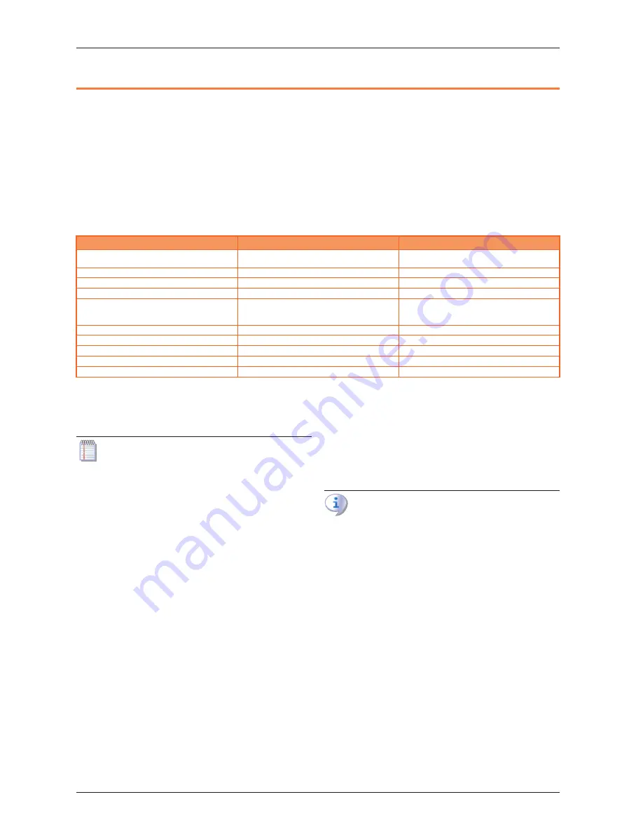
p. 19.
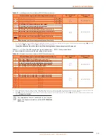
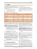
Table 5�1
Heating circuit 3 (or zone 3) preconfiguration (if present)
Preconfiguration
Dependency on parameter
Operating mode
Automatic
(Comfort 6 – 22 Monday – Sunday)
1300
Comfort setpoint
21 °C
1310
Reduced setpoint
18 °C
1312
Protection setpoint
7 °C
1314
Heating curve slope
1.26
(water setpoint around 56 °C with external
temperature -10 °C)
1320
Summer/winter heating limit
18 °C
1330
Flow temp setpoint min
8 °C
1340
Flow temp setpoint max
65 °C
1341
Room influence
20%
1350
Room temperature limitation
2.5 °C
1360
To change the settings of Table 5.1
p. 19, access the
Engineer
menu level, and then the Heating circuit 3 menu; then select
the parameters indicated in Table 5.1
p. 19 and modify them
as desired.
For information about the choice of operating mode and
time programming, refer to par. 5.1.3
p. 19. For infor-
mation on the heating curve settings and the min/max
water temperature setpoint, see par. 5.1.4
p. 19. For
information on the room influence and room tempera-
ture limitation settings, see par. 5.1.5
p. 19.
5.1.3
Selecting the operating mode and time
programming
Refer to par. 5.1.3 of the system controller Installation manual
for the description of the operating modes and for the time pro-
gramming of heating circuits 1 and 2.
For the time programming of heating circuit 3 (obligatory if
the circuit is running in Automatic mode), proceed as indicat-
ed for heating circuit 1 in the above mentioned paragraph of
the system controller Installation manual, but using the Time
prog heating/cooling 3 menu; in this case, use parameters 540
(Preselection), 541 - 546 (period settings) and 555 (Copy).
5.1.4
Setting the heating curve slope and min/max
outlet water setpoints
Refer to Paragraph 5.1.4 of the system controller Installation
manual.
5.1.5
Setting the Room influence and Room
temperature limitation parameters
Refer to Paragraph 5.1.5 of the system controller Installation
manual for a general description of the Room influence and
Room temperature limitation functions, as well as for the set-
tings relating to heating circuits 1 and 2.
Room influence function for heating circuit 3 (if present)
Heating circuit 3, if present, is preconfigured to use this func-
tion in relation to the included room unit 1 temperature reading,
with a mild compensating action (20%), which is suited to many
installations. To modify the degree of influence, or disable the
function entirely:
▶
Select parameter 1350 as described in par. 5.1.2
p. 19 of
this manual, and set the influence percentage (%), or - - - to
disable the function entirely.
Setting a value of 100 % disables the heating curve. It is
best not to use this setting, or even very high influence
percentages. For most applications, do not exceed a set-
ting of 30 %.
Room temperature limitation function for heating circuit 3 (if
present)
Heating circuit 3 is preconfigured to use this function in relation
to the temperature read by room unit 1 (included), with a value
of 2�5 K (the service request is interrupted when room unit 1
reads a temperature 2�5 degrees higher than the setpoint). To
change this setting or disable the function:
▶
Select parameter 1360 as described in par. 5.1.2
p. 19 of
this manual, and set the desired value, or - - - to disable the
function entirely.
5.1.6
Setting the building time constant
Refer to par. 5.1.6 of the System Controller Installation manual.
5.1.7
Choice of installation and use of room units
The system is supplied with a QAA75.611 room unit. The room
unit is preconfigured as Room unit 1 to acquire the room tem-
perature in a reference heated room served by heating circuit 1,
and to influence the regulation of heating circuit 1 accordingly
and, if present, also that of heating circuits 2 and 3 (as described
in par. 5.1.5 of this manual and the System Controller Installation


