General information and system diagrams
6
1
1
GENERAL INFORMATION AND SYSTEM DIAGRAMS
The Expansion kit (KECSK18) of the System Controller for the
models of the K18 family allows the system configurations sup-
ported by it to be extended. In particular, the addition of the
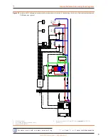
kit allows the types of plumbing diagrams indicated in Figures
1.1
p. 6 and1.2 p. 7 to be set up with regards to the K18
Simplygas unit and those indicated in Figures 1.3
p. 8 and
1.4
p. 9 to be set up with regards to the K18 Hybrigas unit.
The following diagrams intend to show the hydraulic
configurations supported by System controller, in-
cluding the parts to be connected to it. Ancillary hy-
draulic components (expansion tanks, safety valves, etc.)
are only shown as a guide; for the detailed plumbing
layout, refer to the handbook of the K18 range and to
the specific installation manual of the K18 unit used.
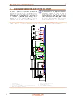
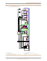
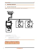
Figure 1�1
System with K18 Simplygas unit, primary water circuit only and three zones, auxiliary boiler and DHW production optionals
A
Unit K18 Simplygas
B
Auxiliary boiler (optional)
C
check valve (to be installed only in the presence of an auxiliary boiler)
D
External water pump (only for C0 versions)
E
By-pass section with overpressure valve
F
Room unit 1 (QAA75.611)
G
Thermostats (with timer) for zones
P
ST
B9
B3
Q3
B
C
ST
ST
GHP'
CSK18
HC1
E
G
F
Q2
HC3
G
Q20
GHP
HC2
G
Q6
A
D
K18 CONTROL CABLE
AUX BOILER
230V W. PUMP
0-10V W. PUMP

