Section PLUMBING INSTALLER
Ed. 04/2012
45
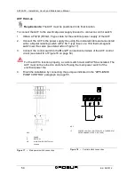
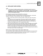
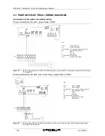
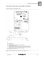
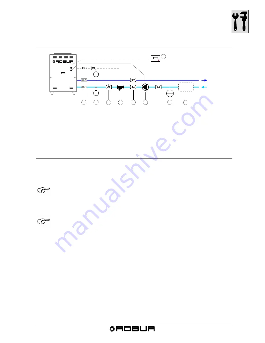
The figure below is a diagram of the ACF60-00 water connections:
Figure 14 –
Water system diagram for one ACF60-00
Accumulation Tank
The configuration of the plant requires a constant circulating of water in the ACF; if
needed, a water tank can be used between the primary and secondary circuits, as
shown for example in Figure 15, page. 46 and “ACCESSORIES” on page 81.
If antifreeze is not used during normal summertime operation, a volume of 70 litres
of water must be used in plant or the primary water circuit for each ACF used. In
this case the diameter of the tubing must be adapted or otherwise an accumulation
tank must be used, as shown in Figure 15 on page 46. This tank must have the
capacity to hold the minimum amount of water required, as mentioned in the note
below.
If more than one ACF is used, add the minimum contents required for each ACF.
The size of the pump and the tubing must be sufficient to supply the nominal water flow
needed for the correct functioning of the ACF. To calculate the internal pressure drop of
the ACF, refer to the “TECHNICAL SPECIFICATIONS” paragraph on page 11.
The use of an accumulation tank on the water circuit is not required for the operation of
the ACF60-00.
®
1
5
6
7
3
4
P
P
2
8
KEY
1
FLEXIBLE CONNECTORS
6
PUMP
2
PRESSURE GAUGES
7
EXPANSION VESSEL
3
FLOW CONTROL VALVE
8
ACCUMULATION TANK
4
WATER FILTER
9
DIRECT DIGITAL CONTROLLER
5
SHUT-OFF VALVE
(available as an accessory)
9
ACF60-00
GAS
DELIVERY
IF USED
RETURN
Summary of Contents for GA ACF60-00
Page 4: ......
Page 6: ...ACF60 00 Installation User s and Maintenance Manual 2 Ed 04 2012 ...
Page 56: ...ACF60 00 Installation User s and Maintenance Manual 52 Ed 04 2012 ...
Page 86: ...ACF60 00 Installation User s and Maintenance Manual 82 Ed 04 2012 ...
Page 91: ...APPENDIX Ed 04 2012 87 APPENDIX DECLARATION OF CONFORMITY ...
Page 92: ...ACF60 00 Installation User s and Maintenance Manual 88 Ed 04 2012 ...
Page 93: ...APPENDIX Ed 04 2012 89 ...
Page 94: ...ACF60 00 Installation User s and Maintenance Manual 90 Ed 04 2012 ...
Page 95: ......


