ACF60-00 – Installation, User’s and Maintenance Manual
68
Ed. 04/2012
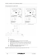
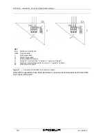
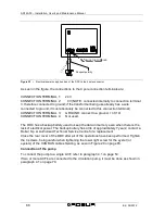
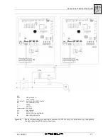
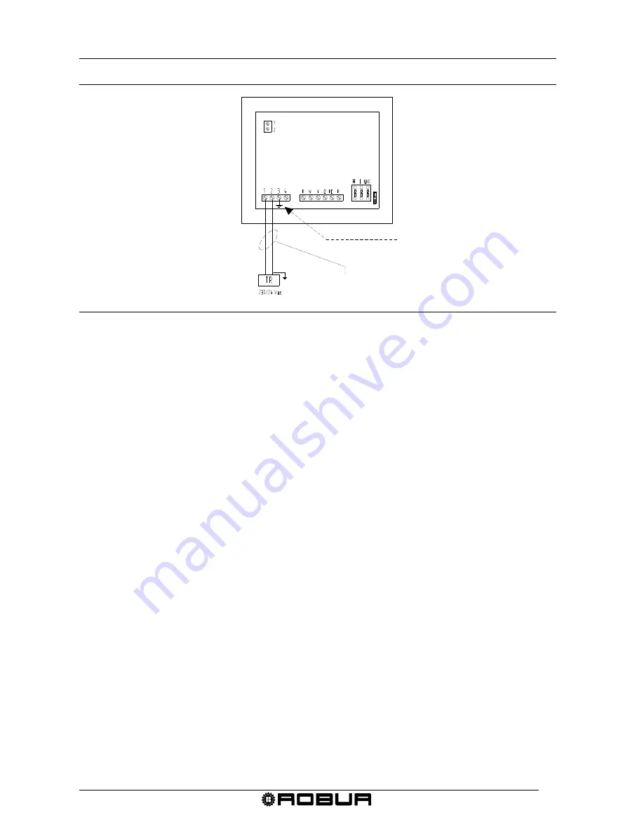
Figure 32 –
Electrical power supply hook-up of the DDC to the 4 pole connector.
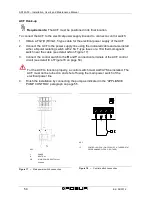
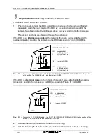
As seen in the figure, the connections to the 4 pole connection terminals are:
CONNECTION TERMINAL 1:
24V
CONNECTION TERMINAL 2:
0V (NOTE: connected internally to connection terminal
3, therefore connected to ground; if the transformer being use already has a wire
connected to ground, it must absolutely be connected to this connection terminal).
CONNECTION TERMINAL 3:
GROUND: connect to a ground, r ≤ 0,1Ω
CONNECTION TERMINAL 4:
Not used.
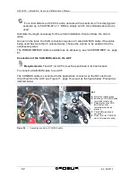
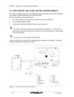
The DDC has a backup battery used to keep the data in memory even when there is the
lack of electrical power. The backup battery has a life of approximately 7 years; contact a
Robur S.p.A. Authorized Technical Service Centre for a replacement.
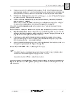
Close the rear cover of the DDC after all of the operations have been performed. Tighten
the 4 screws, being careful when tightening the lower right screw for the eyelet (or
eyelets) of the CAN BUS cable shielding, as seen in Figure 29 on page 65.
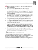
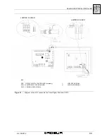
Connection of the pump
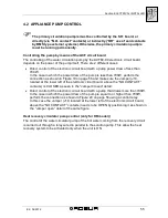
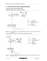
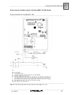
To connect the pump to a single ACF, refer to paragraph 4.1 on page 54.
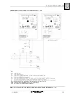
If two or more ACF’s are connected to the circulation pump, it must be done as shown in
paragraph 4.1 on page 70.
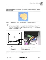
Respect polarity
OBLIGATORY GROUND
Summary of Contents for GA ACF60-00
Page 4: ......
Page 6: ...ACF60 00 Installation User s and Maintenance Manual 2 Ed 04 2012 ...
Page 56: ...ACF60 00 Installation User s and Maintenance Manual 52 Ed 04 2012 ...
Page 86: ...ACF60 00 Installation User s and Maintenance Manual 82 Ed 04 2012 ...
Page 91: ...APPENDIX Ed 04 2012 87 APPENDIX DECLARATION OF CONFORMITY ...
Page 92: ...ACF60 00 Installation User s and Maintenance Manual 88 Ed 04 2012 ...
Page 93: ...APPENDIX Ed 04 2012 89 ...
Page 94: ...ACF60 00 Installation User s and Maintenance Manual 90 Ed 04 2012 ...
Page 95: ......

