4 Electrical installer
Installation, Use and Maintenance Manual – GAHP-A
27
4�4 SET-UP AND CONTROL
Control systems, options (1) (2) (3)
Three separate adjustment systems are provided, each with
specific features, components and diagrams (see 4.4 p. 28,
4.5 p. 28):
▶
System (1), with DDC control (with CAN-BUS connection).
▶
System (2), with CCP/CCI control (with CAN-BUS connec-
tion).
▶
System (3), with an external request.
CAN-BUS communication network
The CAN-BUS communication network, implemented with
the cable of the same name, makes it possible to connect and
remotely control one or more Robur appliances with the DDC or
CCP/CCI control devices.
It entails a certain number of serial nodes, distinguished in:
▶
intermediate nodes, in variable number;
▶
terminal nodes, always and only two (beginning and end);
Each component of the Robur system, appliance (GAHP, GA, AY,
...) or control device (DDC, RB100, RB200, CCI, ...), corresponds to
a node, connected to two more elements (if it is an intermedi-
ate node) or to just one other element (if it is a terminal node)
through two/one CAN-BUS cable section/s, forming an open lin-
ear communication network (never star or loop-shaped).
CAN-BUS signal cable
The DDC or CCP/CCI controllers are connected to the appliance
through the CAN-BUS signal cable, shielded, compliant to Table
4.1 p. 27 (admissible types and maximum distances).
Table 4�1 – CAN BUS cables type
CABLE NAME
SIGNAL / COLOR
MAX LENGTH
Note
Robur
Ordering Code OCVO008
ROBUR NETBUS
H= BLACK
L= WHITE
GND= BROWN
450 m
Honeywell SDS 1620
In all cases the fourth conductor should not be used
BELDEN 3086A
H= BLACK
L= WHITE
GND= BROWN
450 m
TURCK type 530
DeviceNet Mid Cable
TURCK type 5711
H= BLUE
L= WHITE
GND= BLACK
450 m
Honeywell SDS 2022
TURCK type 531
H= BLACK
L= WHITE
GND= BROWN
200 m
For lengths ≤200 m and max 4 nodes (e.g. 1 DDC + 3 GAHP), a
simple 3x0.75 mm shielded cable may even be used.
How to connect the CAN BUS cable to the appliance
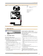
To connect the CAN-BUS cable to the S61 electronic
board (Paragraph 1.5 p. 13), located in the Electrical
Panel inside the unit, (Figure 4.3 p. 27 and 4.4 p. 28):
1. Access the Electrical Board of the appliance accord-
ing to the Procedure 4.2 p. 25);
2. Connect the CAN-BUS cable to terminals GND, L and
H (shielding/ea two signal conductors);
3. Place the CLOSED J10 Jumpers (Detail A) if the node
is terminal (one connected CAN-BUS cable section
only), or OPEN (Detail B) if the node is intermediate
(two connected CAN-BUS cable sections);
4. Connect the DDC or the CCP/CCI to the CAN-BUS
cable according to the instructions in the following
Paragraphs and the DDC or CCP/CCI Manuals.
Figure 4�3 – Electrical wiring diagram
LEGEND
SCH
electronic board
GND
Common data
L
Data signal LOW
H
Data signal HIGH
J1
Jumper CAN-BUS in board
A
Detail case "terminal node" (3 wires; J1=jumper "closed")
B
Detail case "intermediate node" (6 wires; J1=jumper "open")
P8
Port can/connector
Connection cable CAN BUS to electronic board: detail A case "terminal
node", detail B case "intermediate node"
GAHP Configuration (S61) + DDC or CCP/CCI
(Systems (1) and (2) see also Paragraph 1.7 p. 16)


