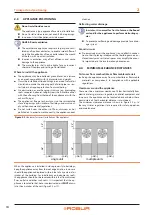
Electrical installer
Installation, use and maintenance manual – GAHP-AR
25
4
Flue gas condensate connection
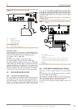
The fitting for flue gas condensate drain is located on the base of
the flue gas exhaust duct (Figure 3.5
▶
The connection of the discharge to the sewerage system
must be made at atmospheric pressure, i.e. by dripping into
a siphoned container connected to the sewerage system.
Flue gas condensate discharge manifold
To make the condensate discharge manifold:
▶
Size the ducts for maximum condensation capacity.
▶
Use plastic materials resistant to acidity pH 3-5.
▶
Provide for min. 1% slope, i.e. 3/8" for each yard of length
(otherwise a booster pump is required).
▶
Prevent freezing.
▶
Dilute, if possible, with domestic waste water (e.g. bath-
rooms, washing machines, dish washers...), basic and neu-
tralising.
3.12
DEFROSTING WATER DRAINAGE
Defrosting
In winter, frost may form on the finned coil and the appli-
ance performs defrosting cycles.
Collection basin and drainage system
▶
Provide for a collection basin or containment rim and a dis-
charge system of the defrosting water, to avoid overflowing,
freezing and damage.
The manufacturer cannot be held responsible for any
damages to persons, animals or goods arising from the
failure to observe this warning.
4
ELECTRICAL INSTALLER
In the following Section please refer to "L" as "L1" and
to "N" as "L2".
4.1
WARNINGS
General warnings
Read the warnings in Chapter III.1
p. 4, providing im-
portant information on regulations and on safety.
Compliance with installation standards
The appliance’s electrical connections and grounding
must be in accordance with the latest edition of the
National Electrical Codes, ANSI/NFPA No. 70 (CSA
Standard C22.1 when installed in Canada)
and with
any local codes. To ensure the electrical safety of this
appliance, it must be correctly connected to an efficient
grounding system. The manufacturer is not responsible
for any damages caused by the failure of the grounding
system.
Installation must comply with applicable regulations in
force, based on the installation Country and site, in mat-
ters of safety, design, implementation and maintenance
of electrical systems.
Installation must also comply with the manufacturer's
provisions.
Live components
After placing the appliance in the final position, and pri-
or to making electrical connections, ensure not to work
on live components.
Grounding
The appliance must be connected to an effective
grounding system, installed in compliance with regula-
tions in force.
It is forbidden to use gas pipes as grounding.
Cable segregation
Keep power cables physically separate from signal ones.
Do not use the power supply switch to turn the ap-
pliance on/off
Never use the external isolation switch (GS) to turn the
appliance on and off, since it may be damaged in the
long run (occasional blackouts are tolerated).
To turn the appliance on and off, exclusively use the suit-
ably provided control device (DDC or external request).
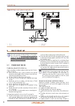
Control of water circulation pump
The water circulation pump of the water/primary circuit
must mandatorily be controlled by the appliance's elec-
tronic board (S61). It is not admissible to start/stop the
circulating pump with no request from the appliance.
Isolation relay
An isolation relay
must
be used to separate the appli-
ance’s transformer from any additional equipment hav-
ing a transformer or damage to the S61 board will occur.
Isolation relays must have a 24 V AC coil, which does not
present more than 0.25 A load to the control circuit.
The manufacturer cannot be held responsible for any
damages to persons, animals or goods due to improper,
erroneous or irrational installation of these appliances.
4.2
ELECTRICAL SYSTEMS
Electrical connections must provide:
A.
power supply (Paragraph 4.3
B.
control system (Paragraph 4.4
How to make connections
All electrical connections must be performed in the electrical
panel of the appliance:
1.
Ensure the appliance's electrical panel is not live.
Summary of Contents for GAHP-AR
Page 43: ......


