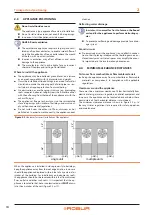
First start-up
Installation, use and maintenance manual – GAHP-AR
31
5
installation.
▶
Gas smell.
▶
Non-compliant mains gas pressure.
▶
Non-compliant flue gas exhaust.
▶
Antifreeze monoethylene glycol not added to the system
water (Paragraph 3.6
p. 22).
▶
All situations that are potentially hazardous.
Should any abnormal installation situations be found, the AT
can carry out the first start-up, but the appliance will be kept
switched off until the user/installer fully follows the manufac-
turer’s directions/instructions.
These situations may be:
▶
Installations which show situations in contradiction to the
directions/instructions of the manufacturer in part or fully.
▶
All situations that may involve operation abnormalities.
Non-compliant system and corrective actions
Should the AT find any non-conformities, he must:
▶
Inform the user/installer of any installation anomaly.
▶
Inform the user/installer of any situation that is judged to be
hazardous for the appliance and for people.
▶
Inform the user/installer of any missing documentation re-
lating to the system.
▶
Indicate, in relation to the reports made, any corrective mea-
sure to be taken on the plant, which the installer will have to
carry out in order to proceed with the first start-up.
Should the AT find any non-conformities, the user/installer is
bound to perform any corrective procedures required by the AT.
After performing the remedial actions (the installer's responsi-
bility), if the AT deems that safety and conformity conditions are
in place, first start-up may be effected.
The positive result of the first start-up (in site) is only reflect-
ing the good operation of the appliance and DDC (if used) but
doesn’t involve any responsibility concerning the correct execu-
tion of the system.
The length of the warranty is dependent upon the
installation and start-up of the unit by Authorized
Technicians (AT). See warranty card for complete de-
tails.
5.2
FIRST START-UP OPERATIONS
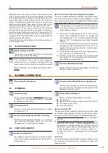
To carry out the first start-up of the appliance, it is necessary to
perform the operations described below, proceeding according
to the following sequential order.
First start-up operations
▶
Open the gas supply tap to the system and check that there
is no smell of gas (indicating possible leaks).
▶
Close the gas tap and check the static gas mains pressure
(Paragraph 5.3
p. 31).
▶
Prepare the appliance for the gas pressure adjustment
(Paragraph 5.4
p. 31).
▶
Power up the appliance, after:
check one final time that there is no smell of gas
activating the external mains switch (GS), provided by
the electrical system installer on a suitable panel, mov-
ing it to the ON position
▶
Power up the DDC, if provided.
▶
Switch on the appliance by means of the provided control
device (DDC or external request).
▶
Adjust the gas pressure to the appliance (Paragraph
p. 31).
▶
Check the dynamic gas mains pressure (if possible on the
appliance that is furthest from the point where the system
is connected to the gas mains), by performing the following
points in order:
stop the appliance
connect the manometer (Paragraph 5.4
reactivate the appliance
read the dynamic mains pressure on the manometer and
check that this value satisfies the requiments of Table
5.1
▶
Carry out the regulation of the operating parameters of the
system.
In the first activation stage, on the display of the electronic
board of the appliance (and/or on the display of the DDC, if any),
an operating code may be displayed (Table 8.1
p. 39).
5.3
CHECK THE STATIC GAS MAINS
PRESSURE
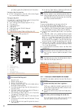
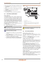
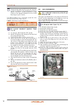
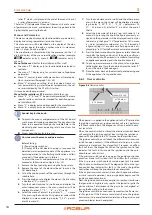
Procedure for checking the static gas mains pressure
(Figure 5.1
1.
Turn main gas valve knob to the "OFF" position.
2.
Remove the plug on the gas pressure intake of gas valve
and attach pressure tap and manometer.
3.
Turn main gas valve knob to the "ON" position.
4.
Read the value of the static gas mains pressure on the
manometer and compare it with the required value:
– 5 inch WC for natural gas
– 11 inch WC for LPG
5.
Turn main gas valve knob to the "OFF" position.
6.
Remove manometer and pressure tap. Replace plug in
gas valve.
5.4
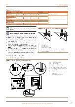
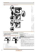
GAS PRESSURE ADJUSTMENT
The manufacturer supplies the appliances already adjusted for a
particular type of gas. The type of gas can be checked and easily
identified by looking at the marking label inside the appliance.
Nevertheless, before starting the appliance it is necessary to
check and adjust if necessary the gas input (HHV) to the burner.
Using the Table 5.1
p. 31 below, arrange the proper manifold
pressure according to the local gas heating value (BTU content
per cubic foot) and specific gravity. Table 5.1
p. 31 is based on
the correct natural gas input (HHV) for the model by manifold
pressure in inches of water column (inch WC).
Table 5.1
Manifold pressure [inch WC] based on gas input (HHV) of
95.500 Btu/hr using a 0.21" nozzle
MJ/m³
Btu/CU.FT.
Specific gravity of natural gas
0.55
0.60
0.65
0.70
35.40
950
3.15
3.43
3.72
4.01
36.33
975
2.99
3.26
3.53
3.80
37.26
1000
2.84
3.10
3.36
3.61
38.19
1025
2.70
2.95
3.20
3.44
39.12
1050
2.58
2.81
3.04
3.28
40.05
1075
2.46
2.68
2.90
3.13
40.98
1100
2.35
2.56
2.77
2.99
41.92
1125
2.24
2.45
2.65
2.86
Our reference:
MJ/m³
Btu/CU.FT.
Specific gravity of natural gas
0.555
37.78
1014
2.77
The conditions referred to by the Table 5.1
p. 31 above are for
the guidance of the installer and the CSA design certification
does not cover the conditions described therein.
Summary of Contents for GAHP-AR
Page 43: ......


