Maintenance
Installation, use and maintenance manual – GAHP-AR
37
7
During the cleaning of the finned coil, always wear safety
googles.
7.2.2
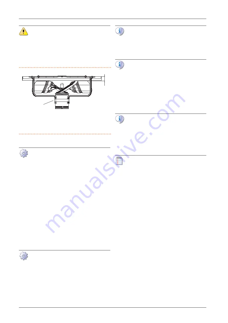
Condenser fan height check
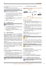
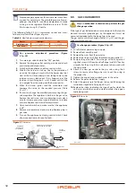
For proper airflow, the distance between the top edge of the fan
blade and the top panel must be 1” 1/4.
If the fan is at an improper height, adjust the location of the
mounting strap around the fan motor.
Figure 7.1
Section view showing proper fan height
1
Section view
2
Mounting strap
3
Fan blade edge - top panel
Note: some details have been removed for clarity
1
”
1/4
1
2
3
7.2.3
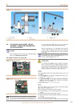
Inspection and cleaning of the flue gas passage
Procedure for inspecting and cleaning the flue gas
passage
1.
Switch off the appliance by means of the suitably provided
control device (DDC or external request) and wait for the end
of the shutdown cycle.
2.
Cut off electric power and gas supply.
3.
Remove the front panel.
4.
Clean the base pan around the generator housing of any
debris.
5.
Look at the flue opening to the right of the generator hous-
ing and clear any debris that may be ostructing the opening.
6.
Look at the air intake chute for combustion air and clear any
debris that may be obstructing the opening.
7.
Replace the front panel.
8.
Restore the gas and electrical supply.
9.
Start the appliance to check for correct operation.
7.2.4
Inspection and cleaning of the burner
Tools needed
▶
Fiber bristle brush
▶
Dust mask (3M #8710 or equal)
▶
Safety googles
▶
Hand tools
Procedure for inspecting and cleaning the burner
1.
Switch off the appliance by means of the suitably provided
control device (DDC or external request) and wait for the end
of the shutdown cycle.
2.
Cut off electric power and gas supply.
3.
Remove the front panel.
4.
Remove bolts and nuts securing the pre-mix blower housing
to the burner tube flange.
5.
Remove screws holding the burner and insulation retaining
straps.
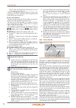
Wear a dust mask (3M #8710 or equal NOISH/MSHA
TC-21C mask) during burner removal, cleaning and as-
sembly operations.
6.
Pry bottom of burner tube out to clear bottom of generator
housing. Pull burner down and out to remove it from gen-
erator housing.
Be careful not to distort or damage the burner tube or
the flame sensor / ignition electrodes assemblies in the
generator housing.
7.
Position the burner tube with open end down.
8.
Clean burner tube ports with fiber bristle brush and shake
any debris out of the tube.
9.
Inspect burner tube gasket that seals the burner tube to the
generator housing and the burner flange gasket that seals
the burner to the pre-mix blower housing. Replace either
gasket if damaged during the burner removal process.
10.
Replace the burner tube in reverse order of removal.
Make sure the two gaskets are positioned correctly and
that the generator housing is properly sealed.
11.
Replace the front panel.
12.
Restore the gas and electrical supply.
13.
Start the appliance to check for correct operation.
7.3
EXTRAORDINARY MAINTENANCE
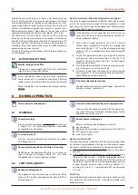
The operations described in this paragraph must be car-
ried out as and when necessary.
▶
Adding water and antifreeze to the system water
If it should be necessary to add water to the system, add a suit-
able quantity, making sure that the minimum pressure is the re-
quired one (Paragraph 3.8
Always add the correct amount of antifreeze glycol, depending
on the minimum external temperature of the installation area
(Paragraph 3.6
p. 22).
7.4
MESSAGES ON THE DISPLAY
4 digit display
The S61 board of the appliance (Paragraph 1.5
p. 12, Figure
5.4
p. 33) is fitted with a 4-digit display, visible through the
sight glass of the front panel.
▶
When the appliance is powered on, all the LEDs switch on for
3 sec, then the board name is displayed.
▶
After another 15 sec, the appliance is ready to operate.
Signals in normal operation
▶
During normal operation, water temperature values alter-
nate on the display: output, input and the difference be-
tween the two.
Signals in the event of fault
In the event of fault the display blinks indicating an operational
code (first letter on the display: "E" = error, or "U" = warning).
The display rotates after the values of the outlet water tempera-
ture, the inlet and the difference between them.
If multiple events are active, they are shown in sequence, or-
dered by increasing code number.
If warning or error events are active, the left green symbol,
Summary of Contents for GAHP-AR
Page 43: ......

