Electrical system installation technician
Ed. 04/2007
31
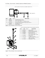
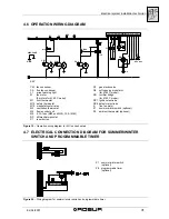
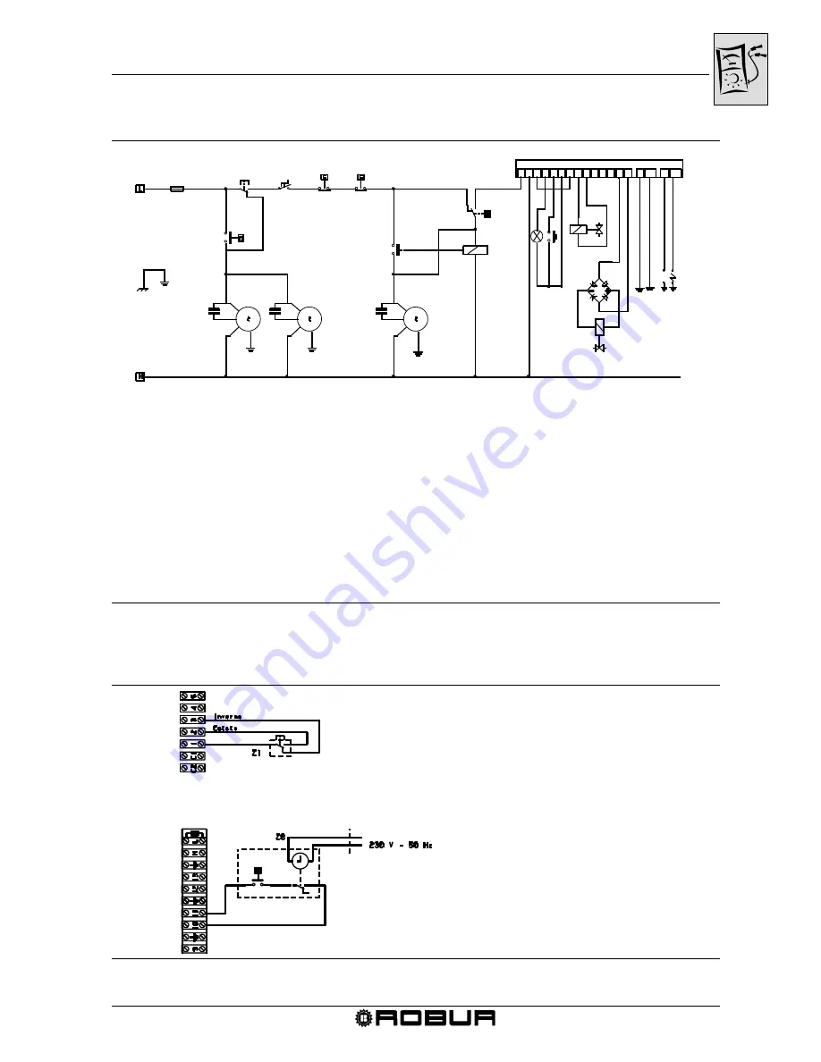
4.6 OPERATION WIRING DIAGRAM
Figure 19
– Operation wiring diagram for M C series heaters
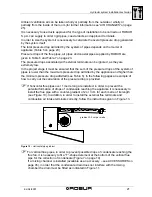
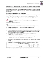
4.7 ELECTRICAL CONNECTION DIAGRAM FOR SUMMER/WINTER
SWITCH AND PROGRAMMABLE TIMER
Figure 20
– Wiring diagram for summer/winter switch and programmable timer
Z1 summer/winter switch
(optional)
Z8 programmable
timer
(optional)
M9
Z1
Z9
M10
M1
RP8 RP7
NP
M12
S
CS
M
CM
M
CM
GND
230V-50HZ
M2
L1
Q2
Q1
RD
M12
P1
1 2 3 4 5 6 7
13
14
15
16
17
18
19
J6
JT1 J5 JT2
M4
KEY
CM fan condenser
Q1 gas electrovalve
CS flue fan condenser
Q2 soft opening modulator
L1
arrest warning light
(for M 60 C model)
M
fan motor
RD rectifier bridge
(2 motors for M 60 C model)
(for M 60 C model)
M1 limit thermostat
RP7 ignition electrode
M10 safety thermostat
RP8 detector electrode
M12 manostat contol relay
S
flue fan motor
M2 ventilation
thermostat
Z1 summer/winter switch (optional)
M4 flame control unit
Z9 ambient thermostat (optional)
M9 6.3 A fuse (M20 and M30), 10 A (M60)
NP differential
manostat
P1 reset
button


