32
5 OPERATION
5.1 Preliminary controls
Warning : Check the correspondence between the process data and the characteristics indicated on
the nameplate of KRVS
-
In case of a storage period longer than 6 months check the preservation condition
-
Verify the alignment between motor and pump.
-
Check if the pipes have been internally cleaned and if obstructions have been removed.
-
Check that all the connections between pump and pipes are tightened and sealed.
-
Check that the shaft rotates freely by hand. If the pump is locked, use lever acting on the elastic coupling of the pump.
-
Check that all the safety protections are enabled.
Warning : Check the efficiency of safety protections
5.2 First start-up
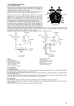
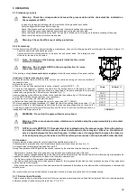
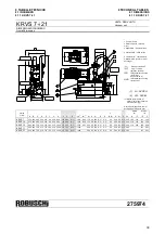
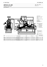
For the first start-up of KRVS or after extraordinary maintenance, carry out the following operations referring to the scheme of figure 1-2:
-
Check the seal of inlet and discharge pipes.
-
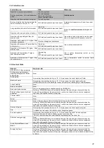
Check electric motor rotating direction by means of a short current pulse. The rotating direction
of the motor fan has to be clockwise.
Note : the arrow on the bearing support indicates the correct
direction of rotation
Warning : Do not rotate KRVS in the wrong direction for more
than a few revolutions
If the rotating is wrong disconnect electric supply and invert the connections of two power cables..
Initial level of liquid in the separator tank
a) Open the service liquid on/off valve (5/8) until you see the liquid coming out from the overflow of
the separator tank.
b) Close the valve (5/8).
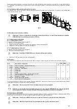
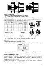
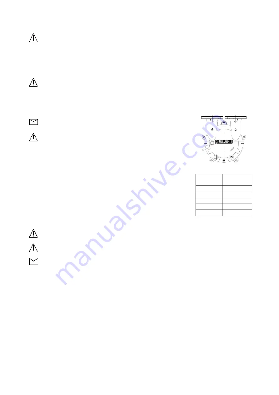
c) Poor in the pump the quantity of liquid shown in table 7 (only for KRVS 7 – 21)
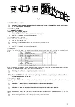
To carry out this operation, introduce the liquid into the suction nozzle of the pump or from the
connection for the VAD valve, this connection is in the middle of the pump casing and it is normally
closed with a plug when the VAD valve is not installed (Fig. 11).
Unscrew the plug or the VAD valve, introduce the liquid and then screw plug or VAD valve again.
For the KRVS 23-60 units this operation is not necessary.
d) Open the on/off valve (5/8) and start the pump.
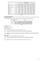
e) Adjust the fresh liquid flow through the valve (4) as per point 5.3.1 (Table 7).
f) For units supplied with heat exchanger (/T) adjust the flow of the cooling liquid using valve (11), as
per point 4.5 (Table 5). Refill separator tank with liquid, which has been evaporated by, the valve (4).
To properly regulate the refill liquid flow, slightly open the valve Vr until the overflow cap shows a
leakage of some drops per minute.
WARNING : Do not run the pump without service liquid
Warning : If there are unusual noises, vibrations or cavitation stop the pump immediately and contact
ROBUSCHI
NOTE: In units KRVS7÷21/T, the separator tank is placed under the vacuum pump. During the start-up
and whenever the suction pressure is close to atmospheric, there may be a little or no circulation of
service liquid between the tank and the pump. In these cases, it is suggested to increase the make-up
of fresh liquid (acting on the valve 4) until the suction pressure does not drop below 900 mbar absolute
5.3 Operation
At every start-up always check the level of initial fill as specified in Section 5.2
If following start-up is made after short breaks (daily frequence) follow the operations d), e), f).
For longer break times follow all steps as from par 5.2
During the operation of KRVS perform the checks required by the maintenance plan keeping in mind that:
- Fast pressure variation floods the pump and may increase power absorption and vibrations.
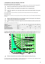
- The pump capacity changes depending on the flow rate and the temperature of the service liquid (for low flow and high temperature the
capacity decreases or the pressure increases into the plant under vacuum).
- Too high service liquid flow increases the absorbed power.
- Hot service liquid containing salts, produces scale deposits; this increases the absorbed current, produces wearing of the components
and the seizure of the impeller.
- If the suction pressure is very low or the pump operates with condensable hot vapours, may start cavitation that produces a characteristic
metallic noise.
We recommend you to read with attention the chapters related to the operating field and to the troubleshooting.
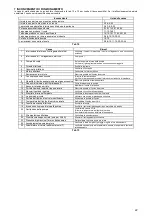
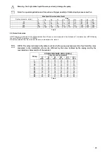
5.3.1 Service liquid flow rate
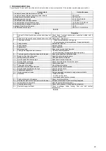
Table 8 shows the service liquid flow rates in m3/h for vacuum and pressure operation with partial recirculation fluid circuit and temperature
difference between fresh and recycled liquid from 5°C to 10°C.
Fig.11
Pump
Volume( l )
RVS 7
2
RVS 14
3
RVS 16
4
RVS 17
5
RVS 21
6
TABELLA 7
Summary of Contents for KRVS
Page 40: ...40 275974 ...


