29
Adjusting air delivery
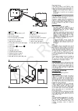
Progressively adjust the end profile of cam 4)(A)
by turning the cam adjustment screws as they
appear through the access opening 6)(A).
- Turn the screws clockwise to increase air
delivery.
- Turn the screws counter-clockwise to reduce
air delivery.
3 - MIN OUTPUT
Min output must be selected within the firing rate
range shown on page 8.
Press button 2)(A)p.26 “output reduction” until
the servomotor has closed the air gate valve
and the gas butterfly valve to 15° (factory set
adjustment).
Adjusting gas delivery
Measure the delivery of gas from the gas meter.
- If this value is to be reduced, decrease the
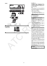
angle of cam I I I (B) slightly by proceeding a
little at a time until the angle is changed from
15° to 13° - 11°....
- If it has to be increased press the button “out-
put increase” 2)(A)p.26 (i.e. open the gas but-
terfly valve by 10-15°), increase the cam I I I
angle (B) with small successive movements,
i.e. take it from angle 15° to 17° - 19°....
Then press the button “output decrease” until
the servomotor is taken to the minimum open-
ing position and measure the gas delivery.
NOTE
The servomotor follows the adjustment of cam
I I I only when the cam angle is reduced. If it is
necessary to increase the cam angle, first
increase the servomotor angle with the key “out-
put increase”, then increase the cam I I I angle,
and at the end bring the servomotor back to the
MIN output position with the key ”output
decrease”.
In order to adjust cam I I I, remove press-fit
cover 1), as shown in fig.(B), extract the relevant
key 2) from inside, and fit it into the keyway in
cam I I I.
Adjustment of air delivery
Progressively adjust the starting profile of cam
4)(A) by turning the screws working through the
access hole 6)(A).
It is preferable not to turn the first screw since
this is used to set the air gate valve to its fully-
closed position.
4 - INTERMEDIATE OUTPUTS
Adjustment of gas delivery
No adjustment of gas delivery is required.
Adjustment of air delivery
Press the key 2)(A)p.26 “output increase” a little
so that a new screw 5)(A) appears in the open-
ing 6)(A), adjust it until optimal combustion is
obtained. Proceed in the same way with the
other screws.
Take care that the cam profile variation is pro-
gressive.
Switch the burner off with the switch 1)(A)p.26,
free the variable profile cam putting the servo-
motor slot 2)(A) in a vertical position and check
more than once, rotating the cam forward and
backward by hand, that the movement is soft
and smooth, without sticking.
As far as is possible, try not to move those
screws at the ends of the cam that were previ-
ously adjusted for the opening of the air gate to
MAX and MIN output.
NOTE
Once you have finished adjusting outputs MAX -
MIN - INTERMEDIATE, check ignition once
again: noise emission at this stage must be
identical to the following stage of operation. If
you notice any sign of pulsations, reduce the
ignition stage delivery.
Regulação do ar
Variar progressivamente o perfil final da leva
4)(A), actuando sobre os parafusos da leva que
aparecem no interior da abertura 6)(A).
- Para aumentar o caudal de ar, roscar os
parafusos.
- Para diminuir o caudal de ar, desenroscar os
parafusos.
3 - POTÊNCIA MÍN
A potência MÍN é escolhida dentro do campo de
trabalho indicado na pág. 8.
Pressionar o botão 2)(A)p.26 “diminuição da
potência” e mantê-lo pressionado até que o ser-
vomotor tenha fechado o registo do ar e a vál-
vula borboleta do gás até 15º (ajuste de
fábrica).
Regulação do gás
Medir o caudal de gás no contador.
- Se deseja diminui-lo, reduzir um pouco o
ângulo da leva I I I (B) através de curtos e
sucessivos deslocamentos, isto é, passando
do ângulo de 15° a 13° - 11°....
- Se deseja aumentá-lo, pressionar um pouco
o botão “aumento de potência” 2)(A)p.26
(abrir de 10-15º a válvula borboleta do gás),
aumentar o ângulo da leva I I I (B) através de
curtos e sucessivos deslocamentos, isto é,
passando do ângulo de 15° a 17° - 19°....
Seguidamente pressionar o botão “diminui-
ção de potência” até levar o servomotor à
posição de abertura mínima e medir o caudal
de gás.
NOTA
El servomotor segue a regulação da leva III só
quando se reduz o ângulo da mesma. Caso
seja necessário aumentar o ângulo da leva, pri-
meiro terá que se aumentar o ângulo do servo-
motor através da tecla “aumento de potência”,
seguidamente aumentar o ângulo da leva I I I e
por último voltar a colocar o servomotor na posi-
ção de potência MÍN com a tecla “diminuição de
potência”.
Para a eventual regulação da leva I I I, retirar a
tampa 1), colocada à pressão, como o indicado
na fig. (B), tirar a cavilha 2) localizada no interior
e introduzi-la no encaixe da leva I I I.
Regulação do ar
Variar progressivamente o perfil inicial da leva
4)(A), actuando sobre os parafusos da leva que
aparecem no interior da abertura 6)(A). Se pos-
sível, não rodar o primeiro parafuso, dado que é
o utilizado para fechar o registo do ar completa-
mente.
4 - POTÊNCIAS INTERMÉDIAS
Regulação do gás
Não é necessário regulação alguma.
Regulação do ar
Pressionar um pouco o botão 2)(A)p.26
“aumento de potência” de forma a que um novo
parafuso 5)(A) apareça no interior da abertura
6)(A) e regular até obter uma combustão
óptima. Proceder da mesma forma com os res-
tantes parafusos. Prestar atenção para que a
variação do perfil da leva seja progressiva
Apagar o queimador através do interruptor
1)(A)p.26 (posição OFF), desbloquear a leva de
perfil variável, colocando a ranhura 2)(A) do
servomotor na posição vertical e verificar várias
vezes, fazendo rodar à mão a leva para a frente
e para trás, que o movimento seja suave e sem
obstáculos.
Se possível, tentar não deslocar os parafusos
dos extremos da leva, regulados anteriormente
para a abertura do registo do ar à potência MÁX
e MÍN.
NOTA
Uma vez terminada a regulação das potências
MÁX - MÍN - INTERMÉDIAS, voltar a verificar o
acendimento: deve produzir-se um ruído pare-
cido ao do funcionamento sucessivo. Se forem
observadas pulsações, reduzir o caudal do
acendimento.
ATC
ROC
Summary of Contents for TECNO 28-GM
Page 39: ...A T C R O C...


